Out-of-plane motion of speckle reduction element

a technology of speckle reduction and out-of-plane motion, which is applied in the direction of printers, instruments, cameras, etc., can solve the problems of thermal load and stress on these components, affecting the design of the projector, and the size and cost of the optical components, and achieves high brightness

Active Publication Date: 2013-02-05
IMAX THEATERS INT
View PDF24 Cites 22 Cited by
  • Summary
  • Abstract
  • Description
  • Claims
  • Application Information

AI Technical Summary

Benefits of technology

[0022]In some embodiments of the present invention, the movement-generating system causes motion of the speckle reduction element in a direction parallel to an optical axis of the speckle reduction element. In some of these embodiments, the motion is within a depth of focus of the projection subsystem. Also in some of these embodiments, the motion is within a depth of focus of the relay system. The motion can further include motion in a direction perpendicular to the optical axis of the speckle reduction element.
[0023]Various embodiments of the present invention are particularly well-suited for spatial light modulators such as DLP devices that modulate light from a laser or other high brightness light source with coherence. Various embodiments of the present invention provide an optical system that allows the use of conventional type projection lens elements and takes advantage of high brightness that can be obtained using laser light.

Problems solved by technology

However, we have determined that these large-etendue light sources impact the projector design in various disadvantageous ways, including size and cost of the optical components, thermal load and stress on these components, and the optical imaging performance and image quality provided by the optics.
For example, the highly angular light incident transiting the spatial light modulator device, and its associated polarization optics, unfavorably impact the projected image quality, with peak contrast and contrast uniformity deficiencies.
In greater detail, the illumination and projection subsystems of digital projection systems are typically more complex than their equivalents in traditional film-based systems.
In particular, in the digital systems, the projection lens systems are often burdened with different and additional requirements compared to the conventional projection optics.
As a result, projection lenses used for large venue or digital cinema projection systems are quite expensive, particularly when compared to conventional projection lenses, such as those used in film-based projectors.
Although the overall system, with the three imaging relays, is increased in complexity, that increased complexity and cost is more than compensated for by the simplicity of the projection lens, which works at a larger F#, without the working distance requirements.
However, lasers also introduce speckle, which occurs as result of the coherent interference of localized reflections from the scattering surface of the display screen.
Speckle is a high contrast granular noise source that significantly degrades image quality.
Speckle reduction provided by a moving diffuser located at an internal intermediate image plane, that is then imaged to a screen, introduces various further problems, including a reduction image quality (resolution or MTF), light loss from diffusion (scatter or diffraction), and a requirement for faster imaging optics to collect diffused light.

Method used


Image

  • Out-of-plane motion of speckle reduction element
  • Out-of-plane motion of speckle reduction element
  • Out-of-plane motion of speckle reduction element

Examples


Embodiment Construction

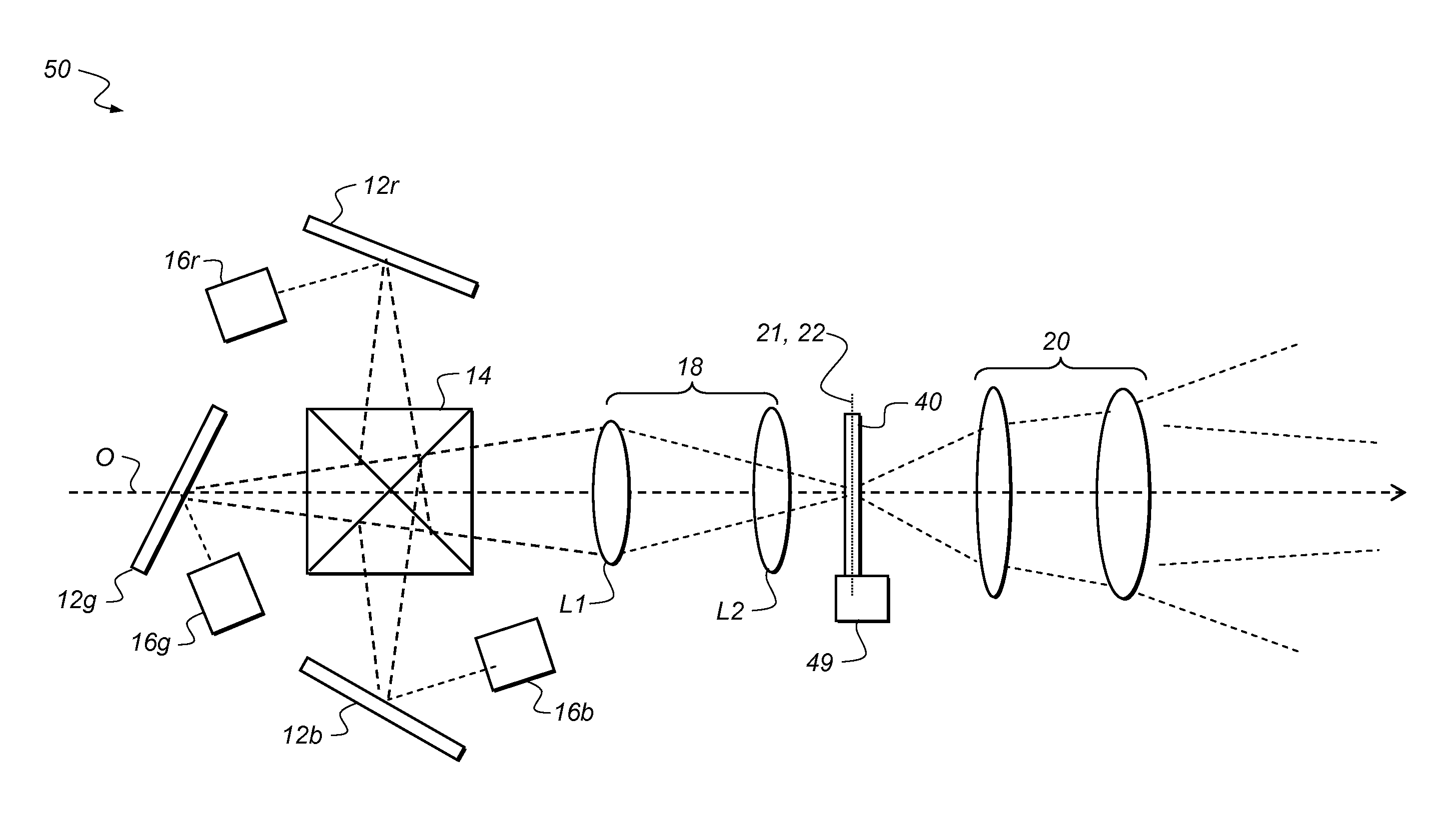
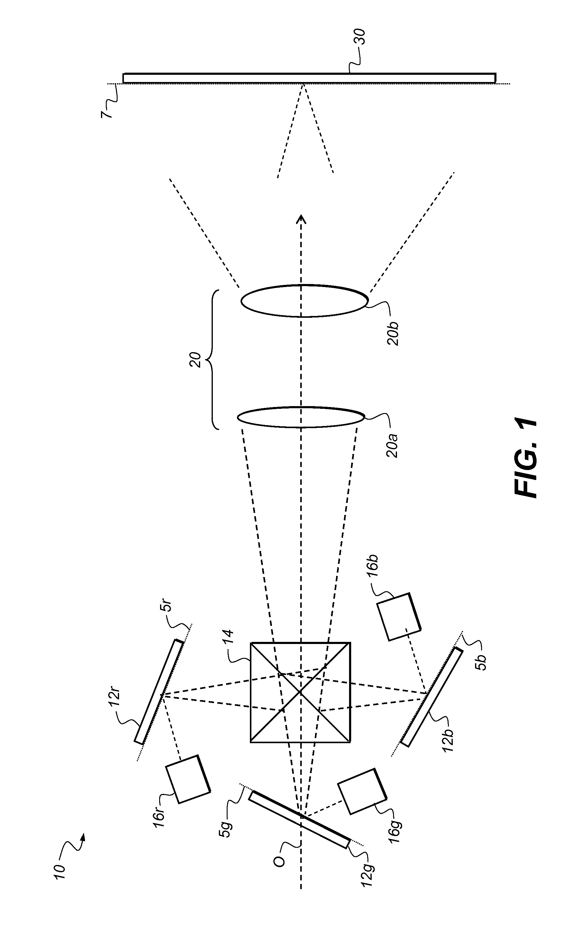
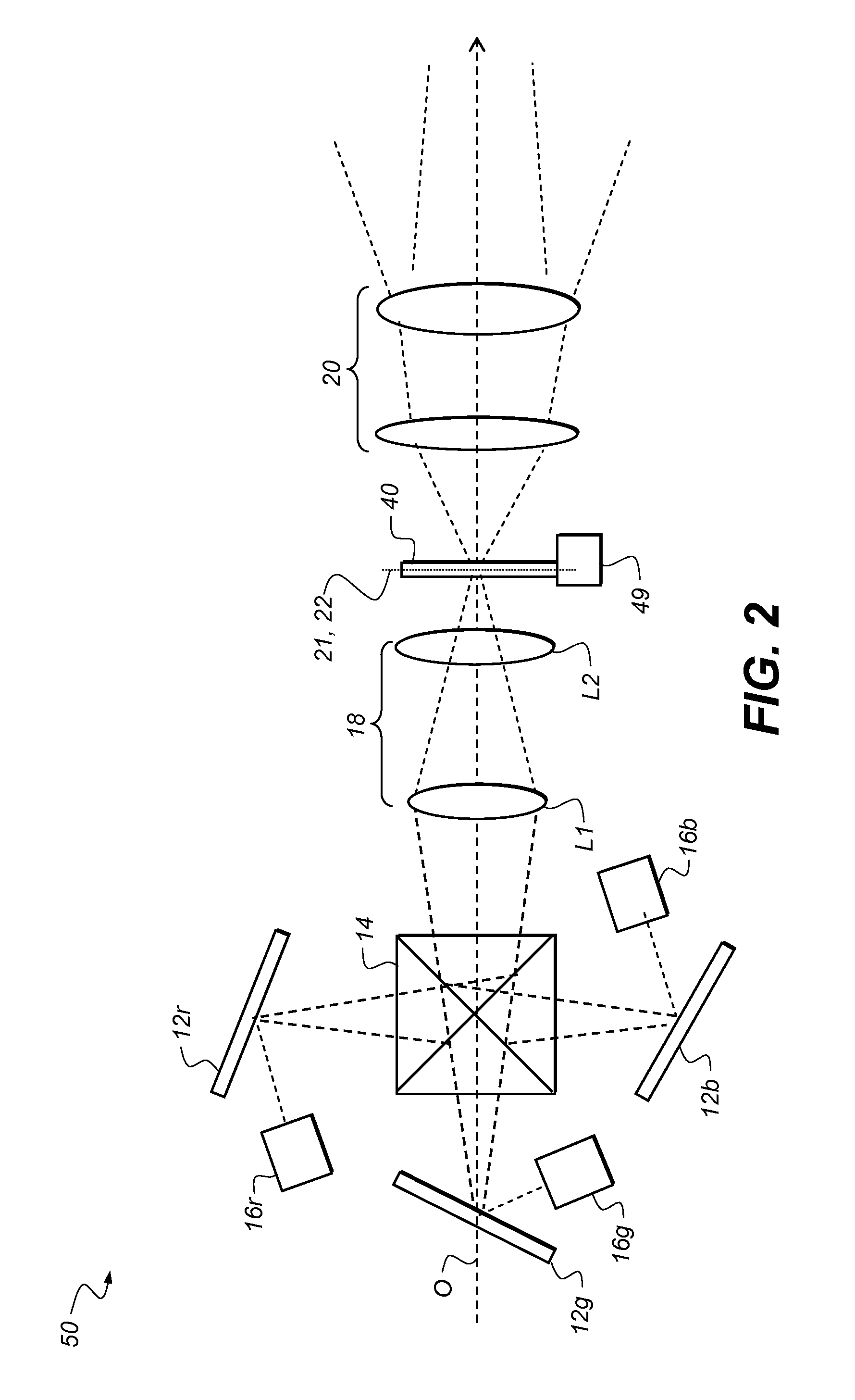
[0034]For the detailed description that follows, it is to be understood that elements not specifically shown or described may take various forms well known to those skilled in the art. Figures shown and described herein are provided to illustrate principles of operation and component relationships along their respective optical paths according to embodiments of the present invention and may not show actual size or scale. Some exaggeration may be necessary in order to emphasize basic structural relationships or principles of operation. In some cases, components that normally lie in the optical path of the projection apparatus are not shown, in order to describe the operation of projection optics more clearly.

[0035]The invention is inclusive of combinations of the embodiments described herein. References to a particular embodiment and the like refer to features that are present in at least one embodiment of the invention. Separate references to “an embodiment” or “particular embodimen...


PUM


Abstract

In a coherent light projection system including an image forming system, a relay system, a speckle reduction element, and a projection subsystem, the relay system can have a first f-number, and the projection subsystem can have a second f-number less than the first f-number. The relay system can have a first working distance, and the projection subsystem can have a second working distance less than the first working distance. The image forming system can project an initial image having a first size, and an intermediate image can have a second size greater than or equal to the first size. The speckle reduction element can have a curved surface through which the intermediate image is transferred. The speckle reduction element can include a lenslet arrangement formed on a surface thereof. The speckle reduction element can be moved in a direction parallel to an optical axis of the speckle reduction element.

Description

CROSS-REFERENCE TO RELATED APPLICATIONS[0001]This application is filed concurrently with and has related subject matter to:[0002]U.S. patent application Ser. No. 12 / 469,318, titled “Projection with Slow Relay and Fast Projection Subsystems”, with Barry Silverstein as the first named inventor;[0003]U.S. patent application Ser. No. 12 / 469,727, titled “Projection with Curved Speckle Reduction Element Surface”, with Barry Silverstein as the first named inventor;[0004]U.S. patent application Ser. No. 12 / 469,737, titled “Projection with Larger Intermediate Image”, with Joseph R. Bietry as the first named inventor; and[0005]U.S. patent application Ser. No. 12 / 469,751, titled “Projection with Lenslet Arrangement on Speckle Reduction Element”, with Barry Silverstein as the first named inventor,[0006]each of which is incorporated herein by reference in its entirety.FIELD OF THE INVENTION[0007]The present invention relates generally to digital image projection and more particularly to a cohere...

Claims


Application Information

Patent Timeline
Patent Type & Authority Patents(United States)
IPC IPC(8): G03B21/14
CPCG02B27/48G03B33/06H04N9/3197G03B21/2033G03B21/208H04N9/3161G02B3/0056G02B5/02
Inventor SILVERSTEIN, BARRY D.NOTHHARD, GARY E.BIETRY, JOSEPH R.METZGER, ROBERTKURTZ, ANDREW F.
Owner IMAX THEATERS INT
Why Eureka
Try Eureka