

Reflective electrode, display device, and method for producing display device
a technology of display device and reflector, which is applied in the direction of discharge tube luminescnet screen, non-electron-emitting electrode material, instruments, etc., can solve the problems of low reflectance, difficult to see the display in dark surroundings, and unsuitable small appliances, etc., to achieve high reflectance, low contact resistance, and electric resistivity.
- Summary
- Abstract
- Description
- Claims
- Application Information
AI Technical Summary
Benefits of technology
Problems solved by technology
Method used
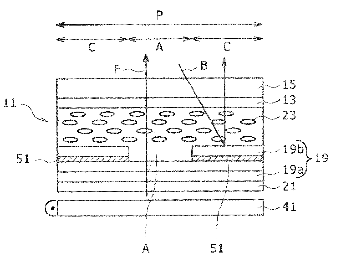
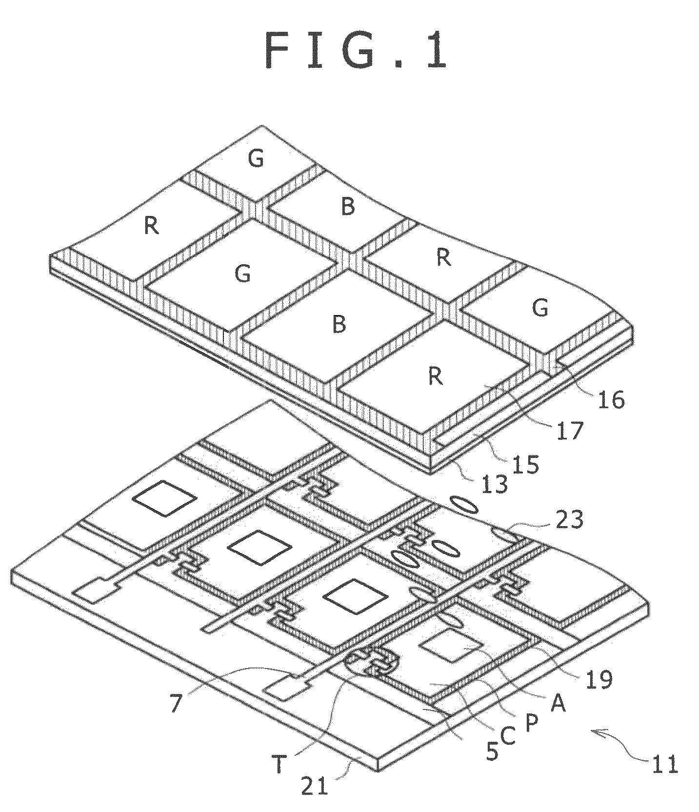
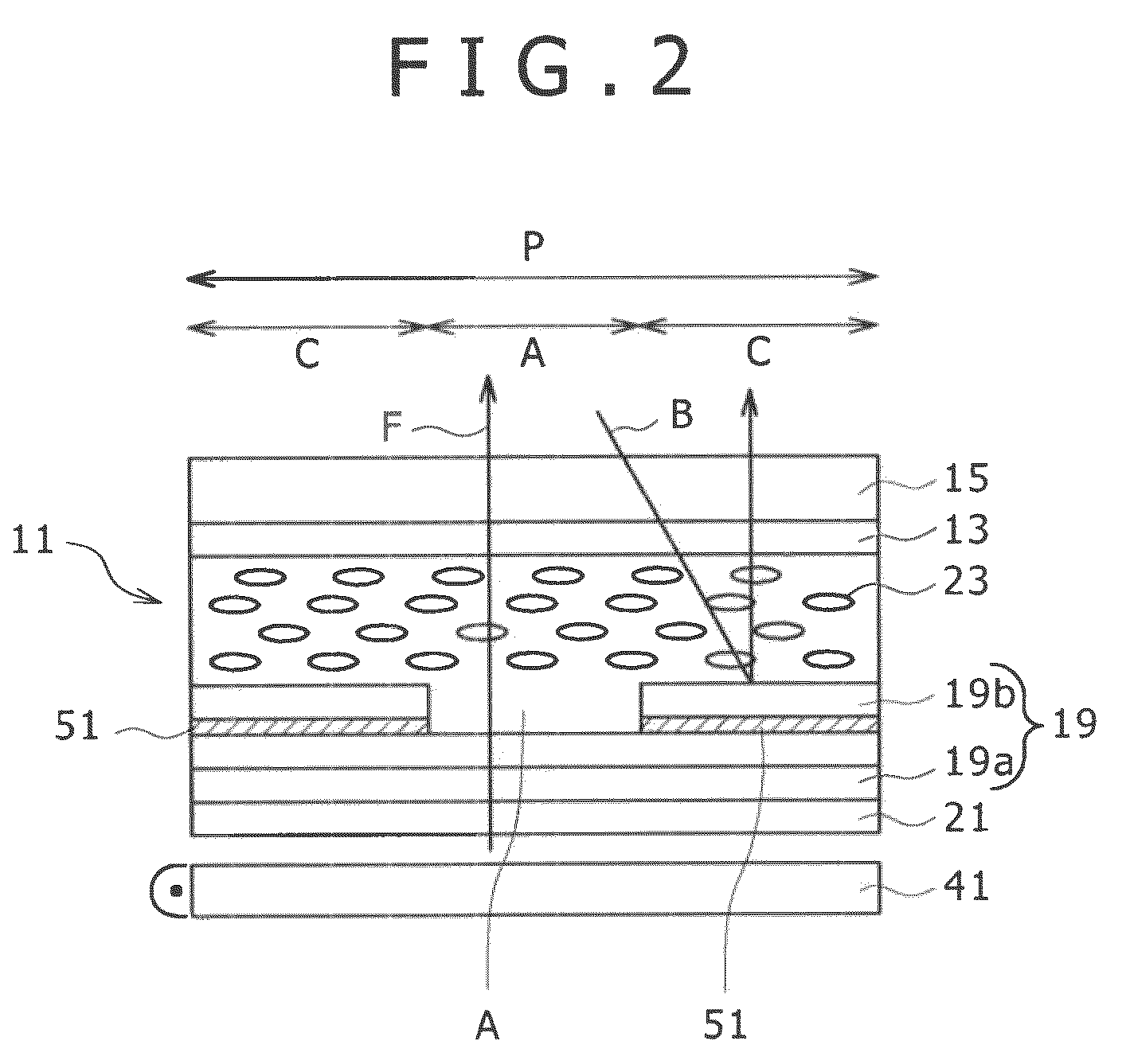
Image

Examples
experimental example 1
[0108]The first production method was investigated in this experimental example.
[0109]Specifically, a series of layer of Al—Ni—La alloys as materials for a reflective electrode was deposited through sputter deposition each on an alkali-free glass plate (thickness (gauge) 0.7 mm) substrate. The sputter deposition was performed under conditions of an Ar atmosphere at a pressure of 1 mTorr and a power of 100 W. In each sample, the thickness of the Al—Ni—La alloy layer was controlled to be about 100 nm. The Ni contents and La contents in the Al—Ni—La alloy layers are shown in Table 1.
[0110]Next, samples of the Al—Ni—La alloy layers were divided into two groups, i.e., those subjected to a heat treatment and those not subjected to a heat treatment. The heat treatment was performed at a temperature given in Table 1 in a vacuum atmosphere (with a degree of vacuum of equal to or less than 3×10⁻⁴ Pa) or in a N2 atmosphere for 1 hour.
[0111]Next, non-treated and heat-treated Al—Ni—La alloy laye...
experimental example 2
[0121]The second production method was investigated in this experimental example.
[0122]Specifically, samples according to the present invention (Examples) were prepared by depositing an Al—Ni—La alloy layer (thickness: about 100 nm) and an ITO film (thickness: about 50 nm) on an alkali-free glass plate (thickness (gauge) 0.7 mm) by the procedure of Experimental Example 1, except for not performing a heat treatment but performing the deposition of ITO while using an Ar sputtering gas further containing 12% of N2 gas in terms of ratio by volume flow rate. For comparison, comparative samples (Comparative Examples) were prepared by performing the deposition of ITO in an atmosphere of Ar gas alone.
[0123]Of these samples according to the present invention and comparative samples, the contact resistance, and the [O] / [Al] ratios and thickness in its thinnest portion of the aluminum oxide layer were measured by the procedure of Experimental Example 1.
[0124]As a result, the samples according ...
experimental example 3
[0125]The third production method was investigated in this experimental example.
[0126]Specifically, an Al—Ni—La alloy layer (thickness: about 100 nm) and an ITO film (thickness: about 50 nm) were deposited on an alkali-free glass plate (thickness (gauge) 0.7 mm) by the procedure of Experimental Example 1, except for not performing the heat treatment. Instead of the heat treatment, samples were placed in a sputter deposition system for ITO film, Ar gas was introduced in the system, and the sample surfaces were subjected to reverse sputtering with Ar for 10 seconds while changing (reversing) the polarity of sputtering. The reverse sputtering was performed under conditions of Ar atmosphere at a pressure of 1 mmTorr and a power of 100 W. Thereafter the polarity of sputtering was turned back, and an ITO film was deposited by the procedure of Experimental Example 1 and thereby yielded samples according to the present invention. For comparison, comparative samples were prepared without per...
PUM
| Property | Measurement | Unit |
|---|---|---|
| thickness | aaaaa | aaaaa |
| temperature | aaaaa | aaaaa |
| electrode potential | aaaaa | aaaaa |
Abstract
Description
Claims
Application Information