
Ultrapure synthetic carbon materials

a synthetic carbon and carbon material technology, applied in the field of ultra-capture synthetic carbon materials, can solve problems such as the degradation of other components, and achieve the effect of improving operation and shortening life span

Active Publication Date: 2013-03-26
BASF SE
View PDF82 Cites 108 Cited by
  • Summary
  • Abstract
  • Description
  • Claims
  • Application Information

AI Technical Summary

Benefits of technology

[0013]In general terms, the present invention is directed to ultrapure synthetic carbon materials, as well as to methods for making such materials and to devices containing the same. Such materials find application in the context of electrical storage and distribution devices, particularly for use in electrodes for EDLCs and batteries. Existing carbon materials contain residual levels of various impurities (e.g., chlorine, sulfur, metals, etc.) which are known to decrease the breakdown voltage of the electrolyte in which the electrodes are immersed. Thus, existing electrodes must be operated at lower voltages and have a shorter life span than devices comprising the ultrapure synthetic carbon materials of this invention. The impurities in carbon electrodes also contribute to degradation of other components within an EDLC or battery. For example the porous membrane which separates the two carbon electrodes in an EDLC may be degraded by chlorine or other impurities within the carbon electrode. The ultrapure synthetic carbon materials disclosed herein are significantly more pure than any known carbon materials and thus improve the operation of any number of electrical storage and / or distribution devices
[0035]The ultrapure synthetic amorphous carbon material finds utility in any number of electrical storage and distribution devices. The combination of ultrapurity, high porosity and high surface area allows for the preparation of electrical storage and distribution devices having properties superior to known devices. The devices comprising the ultrapure synthetic amorphous carbon material are capable of operation at higher voltages for longer periods of time at higher temperatures than comparable devices prepared from lower purity carbon.

Problems solved by technology

The impurities in carbon electrodes also contribute to degradation of other components within an EDLC or battery.

Method used


Image

  • Ultrapure synthetic carbon materials
  • Ultrapure synthetic carbon materials
  • Ultrapure synthetic carbon materials

Examples


example 1

Production of RF Gels from 100% Acetic Acid Solution

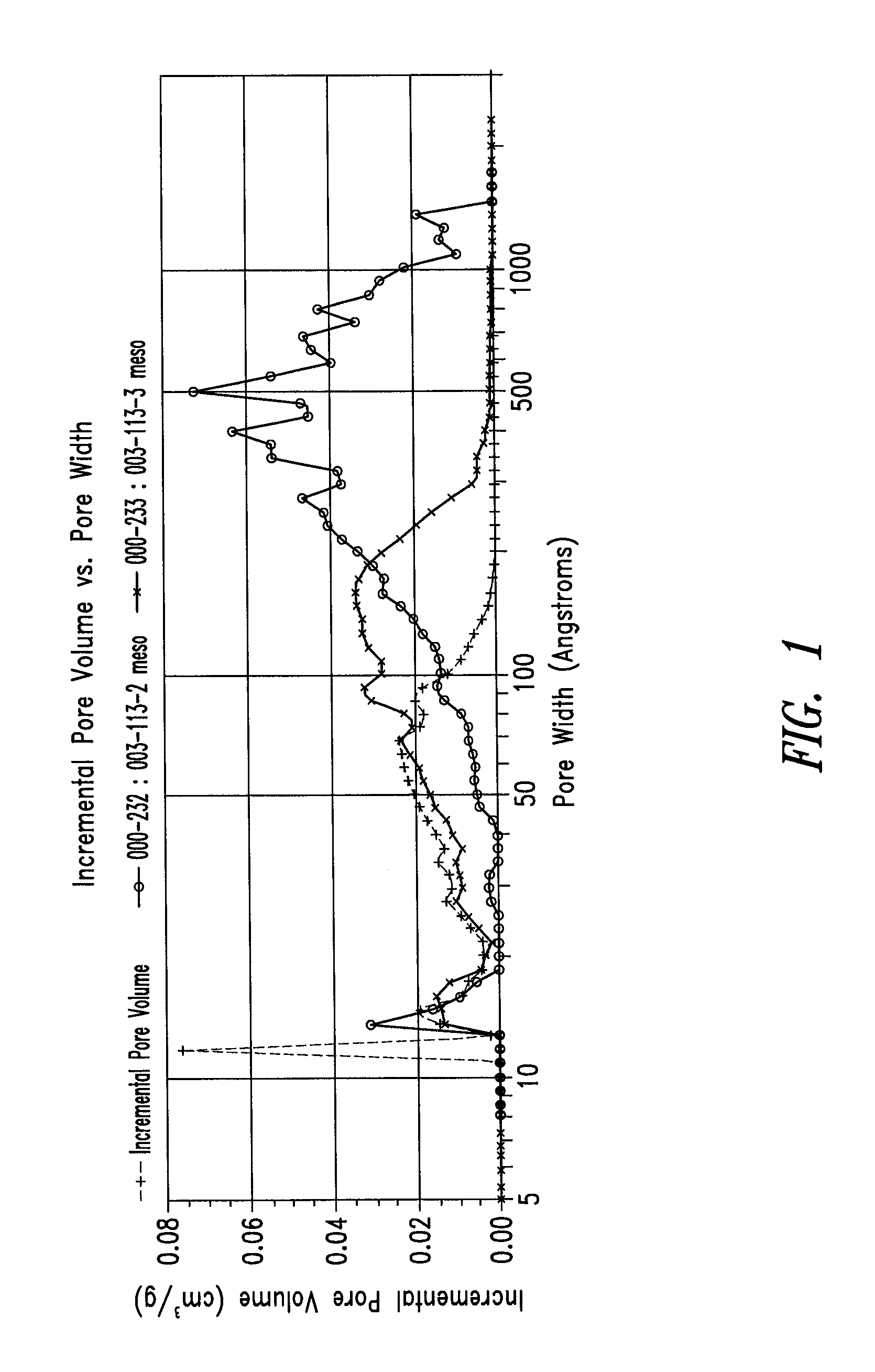
[0252]A series of RF gels were made form “neat” acetic acid (i.e., anhydrous). Three samples were produced with varying levels of ammonium carbonate (as “catalyst”): none, and ˜100 and ˜25 R / C. These samples were crushed by hand to create particles, frozen by immersion in liquid nitrogen, and lyophilized. A summary of these formulations and their specific surface areas is presented in Table 1. All three samples were monolithic and orange in color. Color intensity was greater for those samples containing ammonium carbonate. The specific surface area of the three samples were between 597 and 644 m2 / g.

[0253]FIG. 1 presents the incremental pore volume vs. pore width for these samples. The sample prepared without catalyst had a DFT average pore size of about 185 Å, with a broad peak between about 100 and 1000 Å, and a secondary peak at about 14 Å (and was relatively devoid of pore volume in between). In contrast, as catalyst was added t...

example 2

Production of RF Gels from 90:10 Acetic Acid:Water (vol:vol) Solution

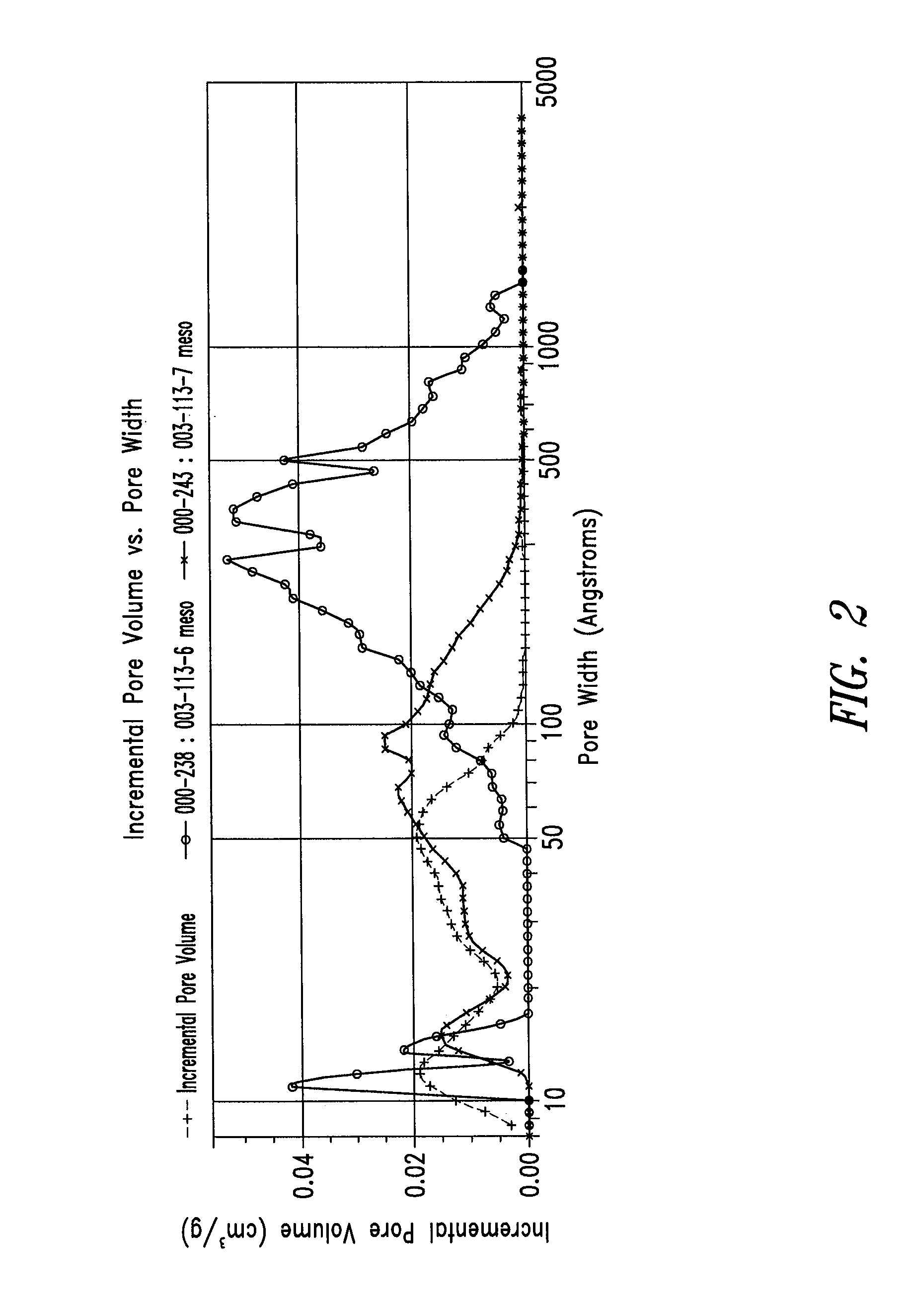
[0255]In order to examine the effect of addition of a small amount of water in the system, a series of RF gels were produced from a mixed solvent of acetic acid:water in a 90:10 vol:vol ratio (prior to addition of formaldehyde). Three samples were produced with varying levels of ammonium carbonate: none, and ˜100 and ˜25 R / C. These samples were crushed by hand to create particles, frozen by immersion in liquid nitrogen, and lyophilized.

[0256]A summary of these formulations and their specific surface areas are presented in Table 2. All three samples were monolithic and orange in color. Color intensity was greater for those samples containing ammonium carbonate. The specific surface area of the three samples was between 586 and 653 m2 / g.

[0257]FIG. 2 presents the incremental pore volume vs. pore width for these samples. The sample prepared without catalyst had a DFT average pore size of about 160 Å, with a broad peak ...

example 3

Production of RF Gels from 50:50 Acetic Acid:Water (vol:vol) Solution

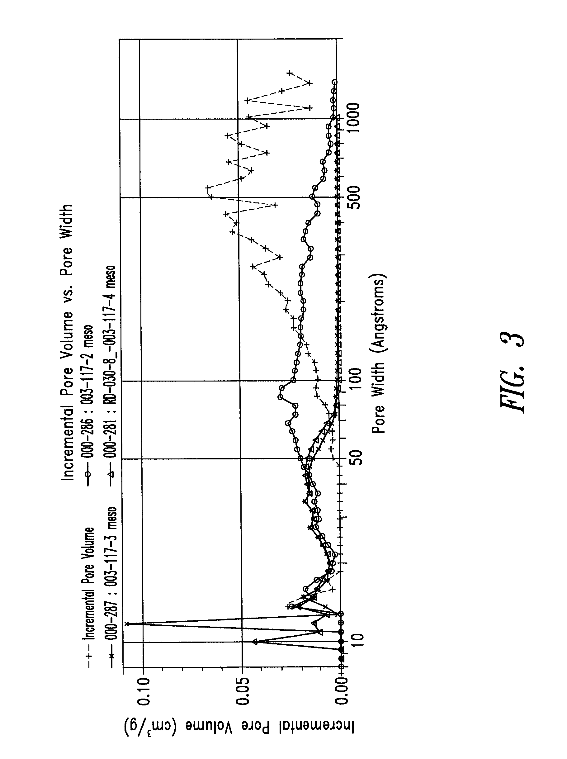
[0259]To further examine the effect of addition of water, a series of RF gels were produced from 50:50 acetic acid:water (prior to addition of formaldehyde). Three samples were produced with varying levels of ammonium carbonate: none, and ˜100 and ˜25 R / C. A fourth sample was made with the addition of ammonium acetate at a ratio of ˜25 R / C. These samples were crushed by hand to create particles, frozen by immersion in liquid nitrogen, and lyophilized.

[0260]A summary of these formulations and their specific surface areas are presented in Table 3. All four samples were monolithic and orange in color. Color intensity was greater for those samples containing ammonium carbonate or ammonium acetate. The specific surface area of the four samples was between 560 and 693 m2 / g.

[0261]FIG. 3 presents the incremental pore volume vs. pore width for these samples. The sample prepared without catalyst had a DFT average pore size o...


PUM

PropertyMeasurementUnit
atomic numbersaaaaaaaaaa
BET specific surface areaaaaaaaaaaa
atomic numberaaaaaaaaaa

Abstract

The present application is generally directed to ultrapure synthetic carbon materials having both high surface area and high porosity, ultrapure polymer gels and devices containing the same. The disclosed ultrapure synthetic carbon materials find utility in any number of devices, for example, in electric double layer capacitance devices and batteries. Methods for making ultrapure synthetic carbon materials and ultrapure polymer gels are also disclosed.

Description

CROSS-REFERENCES TO RELATED APPLICATIONS[0001]The present application claims the benefit under 35 U.S.C. §119(e) of U.S. Provisional Patent Application No. 61 / 222,431 filed on Jul. 1, 2009; U.S. Provisional Patent Application No. 61 / 255,037 filed on Oct. 26, 2009; U.S. Provisional Patent Application No. 61 / 255,054 filed on Oct. 26, 2009; and U.S. Provisional Patent Application No. 61 / 261,703 filed on Nov. 16, 2009; all of which are incorporated herein by reference in their entireties.STATEMENT OF GOVERNMENT INTEREST[0002]Partial funding of the work described herein was provided by the U.S. Government under Contract No. W15P7T-09-C-S311 provided by the Department of Defense. The U.S. Government may have certain rights in this invention.BACKGROUND[0003]1. Technical Field[0004]The present invention generally relates to ultrapure synthetic carbon materials, methods for making the same and devices containing the same.[0005]2. Description of the Related Art[0006]Activated carbon is common...

Claims


Application Information

Patent Timeline
Patent Type & Authority Patents(United States)
IPC IPC(8): H01M4/38C01B31/00
CPCC01B31/00C01B31/02H01M4/583H01G11/34H01G11/24H01G11/48H01G9/042Y02E60/13B29C70/00B29C70/42C01B32/00C01B32/05C01B32/318C01P2006/12C01P2006/80H01G11/32H01M4/96H01M10/052H01M10/06H01M2220/20H01M2220/30Y02E60/10Y02E60/50
Inventor FEAVER, AARON M.COSTANTINO, HENRY R.SCOTT, WILLIAM D.
Owner BASF SE
Learn More