

Process for downstream recovery of nitroalkane using dividing wall column
a technology of nitroalkane and dividing wall column, which is applied in the direction of separation process, organic chemistry, chemistry apparatus and process, etc., can solve the problems of high reflux ratio, difficult separation, and large energy consumption
- Summary
- Abstract
- Description
- Claims
- Application Information
AI Technical Summary
Benefits of technology
Problems solved by technology
Method used
Image

Examples
example 1
High Pressure Nitration of Propane
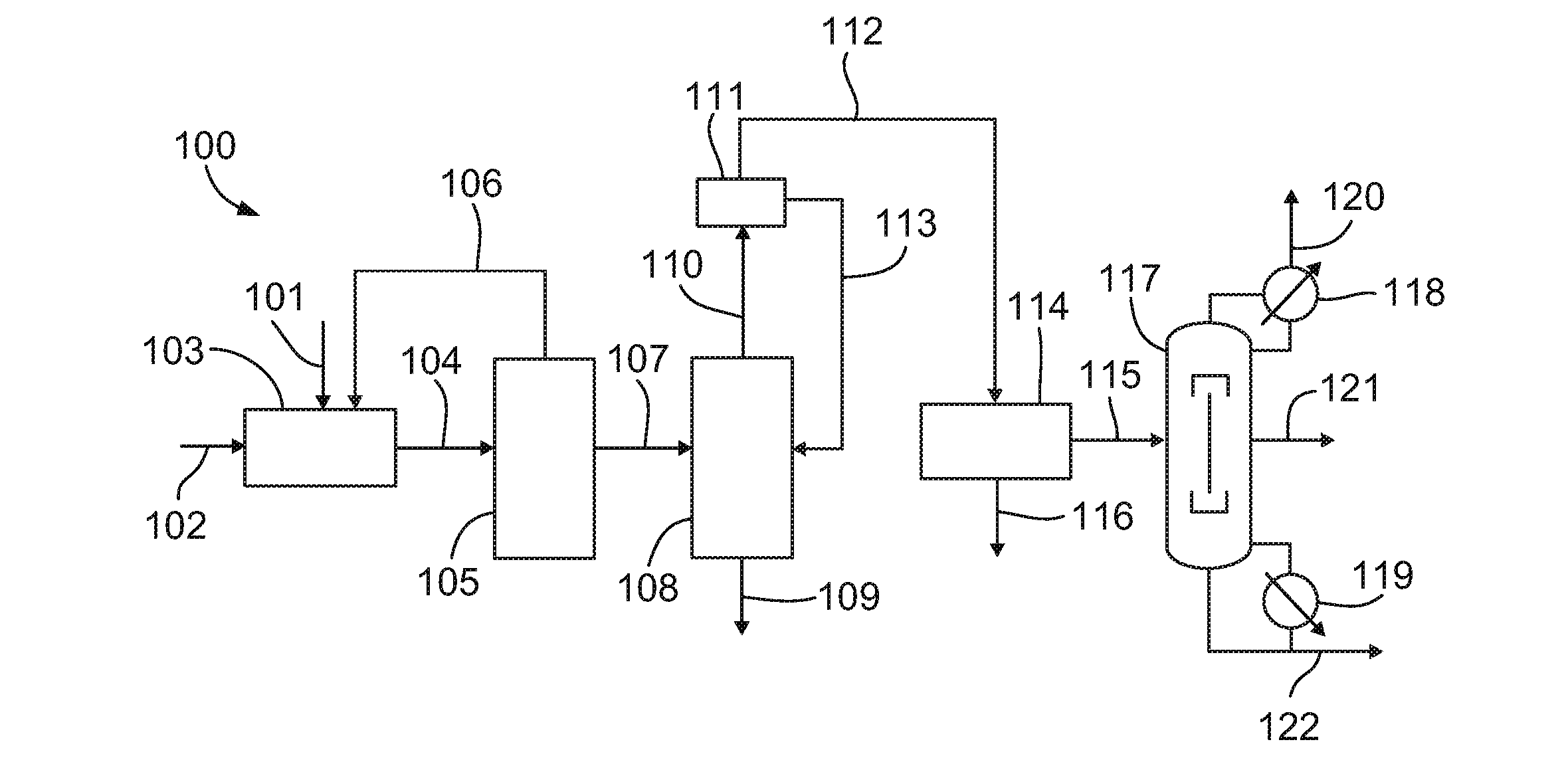
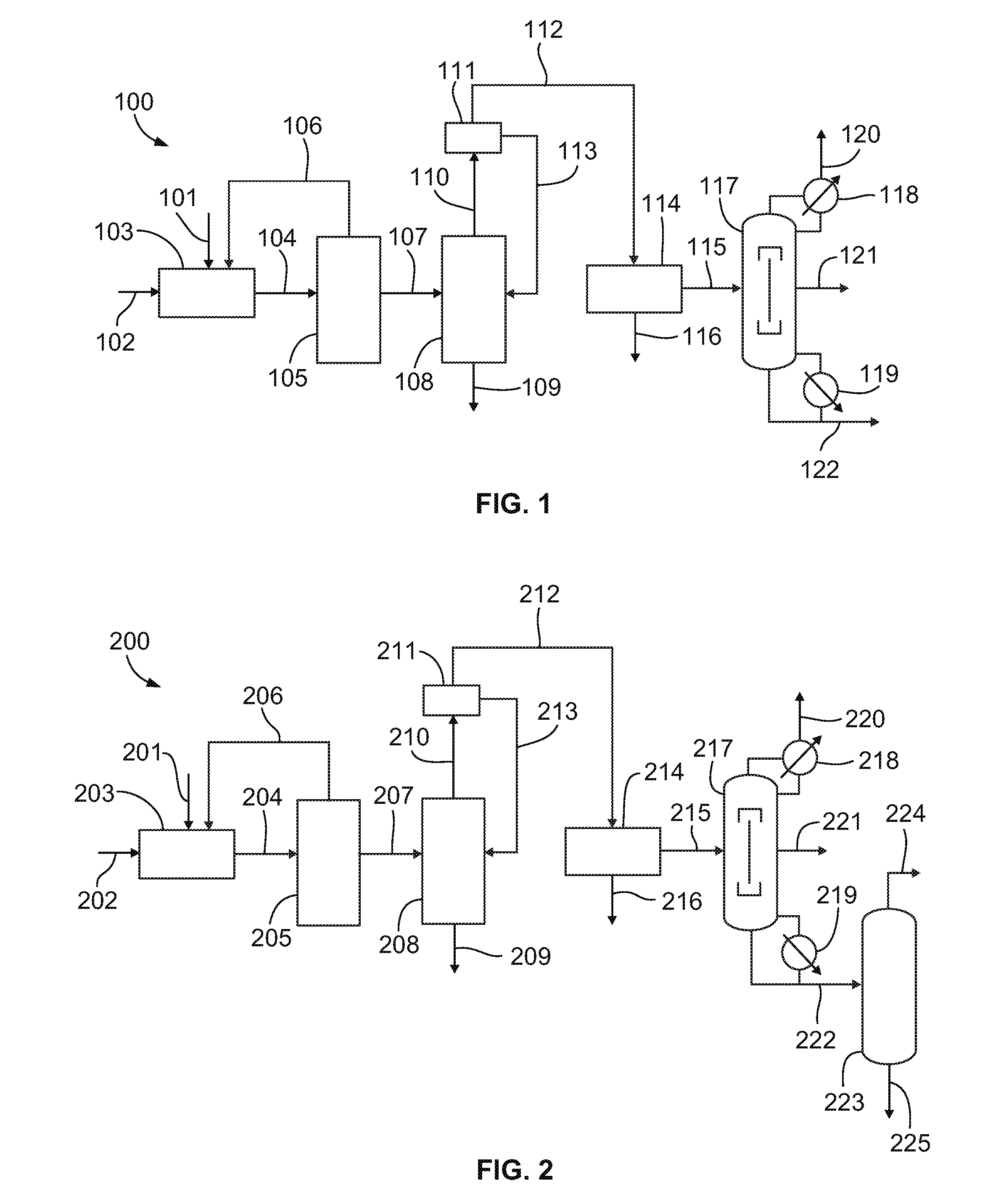
[0059]Propane is reacted with 30 weight percent aqueous nitric acid at a reactor pressure of about 1200 psi (77.4 atm), an average reaction temperature of about 250 degrees Celsius (a range of 220 to 290 degrees Celsius), a residence time of about 120 seconds, and a propane to nitric acid mole ratio of about 1.5:1 in a high pressure nitration process to produce a product stream. This product stream is then sent to a dividing wall column (DWC). The major components of the product stream feed to the DWC are summarized in Table 1 below. The scheme is designed for a 2-nitropropane production rate of 5420 lb / h. and consists of a relatively small fraction of components lighter than 2-nitropropane, followed by a large mole fraction of the desired product 2-nitropropane, and then a relatively small amount of components heavier than 2-nitropropane.
[0060]
TABLE 1Feed to the DWC in a high pressure nitration processTemperature, ° C. 21Pressure, atm 1Mass flow, l...
example 2
Vapor Phase Nitration of Propane
[0066]Vapor phase nitration has a lower selectivity towards 2-nitropropane. Propane is reacted with 70 weight percent aqueous nitric acid at a reactor pressure of about 185 psi (9.7 atm), an average reaction temperature of about 370 degrees Celsius, a residence time of about 2.3 seconds, and a propane to nitric acid mole ratio of about 4:1 in a vapor phase nitration process to produce an product stream. Table 3 summarizes a typical composition of the product stream coming out of the water-wash neutralization section from a vapor phase nitration process compared with the stream composition of a similar stream from a high pressure nitration process.
[0067]
TABLE 3Composition of key components in input to thedownstream purification section of vapor phasenitration and high pressure nitration processWeight %ComponentsVaporHigh PressureNitromethane20.41.01Nitroethane5.00.62-nitropropane56.583.31-nitropropane15.77.6
[0068]This product stream is then sent to a d...
example 3
Modified High Pressure Nitration
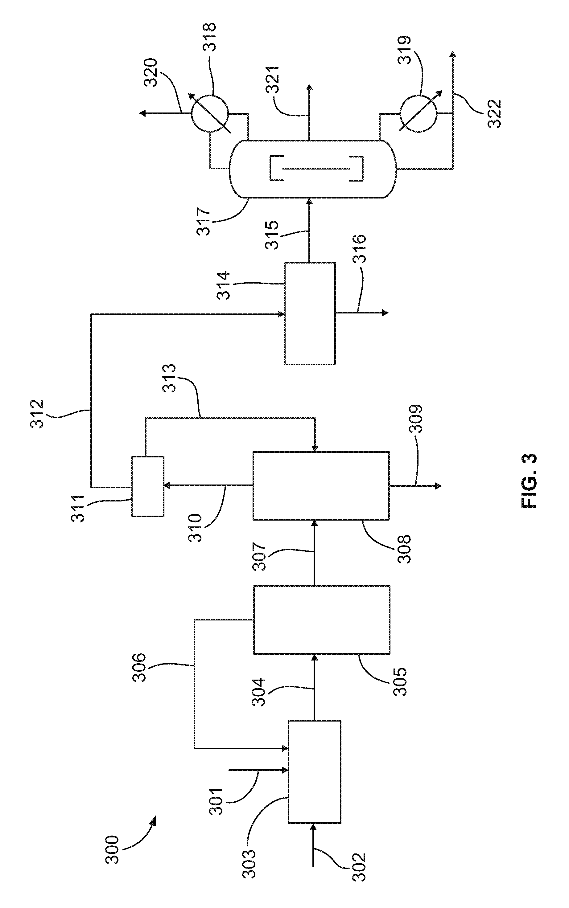
[0075]In a modified version of the high pressure process, the main oxidation byproducts (carboxylic acids) are recycled to produce valuable nitroparaffin products rather than discarded to wastewater treatment. Propane is reacted with 30 weight percent nitric acid at a reactor pressure of about 1200 psi (77.4 atm), an average reaction temperature of about 235 degrees Celsius (a range of 180 to 290 degrees Celsius), a residence time of about 120 seconds, and a propane to nitric acid mole ratio of about 0.5:1. The main byproduct of propane nitration is acetic acid in high pressure nitration (acetic acid may also be added at startup in order to more quickly obtain a steady-state process). This byproduct, when concentrated and recycled to the reactor yields significant amounts of nitromethane at typical high pressure nitration process conditions. Nitromethane selectivity is about 55%, which is about 30% higher than the maximum achievable using the commerci...
PUM
| Property | Measurement | Unit |
|---|---|---|
| temperature | aaaaa | aaaaa |
| temperature | aaaaa | aaaaa |
| temperature | aaaaa | aaaaa |
Abstract
Description
Claims
Application Information