
Amplitude control system and method for communication systems

a communication system and amplitude control technology, applied in gated amplifiers, limiting amplitude without controlling loops, electrical apparatus, etc., can solve the problems of low transmitter efficiency, difficulty in achieving high average pa (power amplifier) efficiency, and low transmitter efficiency

Active Publication Date: 2013-04-30
APPLE INC
View PDF5 Cites 8 Cited by
  • Summary
  • Abstract
  • Description
  • Claims
  • Application Information

AI Technical Summary

Benefits of technology

The present invention relates to a modulation system and method for improving the efficiency of transmitting high bandwidth RF signals with non-constant envelope. The invention addresses the problem of low efficiency in linear transmitters when transmitting high PAPR signals. The invention proposes a polar transmitter architecture that can theoretically transmit high PAPR signals with very high efficiency. The invention also proposes a modulation system and method that can improve the efficiency of linear transmitters for high PAPR signals.

Problems solved by technology

The conventional RF transmitter architectures and circuit techniques, however, have not achieved high efficiency when transmitting high bandwidth NCE signals.
In particular, achieving high average PA (Power Amplifier) efficiency generally becomes more difficult as the Peak to Average Power Ratio (PAPR) of the transmitted signal increases, especially at high bandwidth.
Low transmitter efficiency is a significant problem in portable wireless devices in which battery lifetime is especially important.
The summation signal, however, typically does not have sufficient power for direct transmission.
The efficiency of the Class A amplifier, however, falls very quickly as the output signal amplitude drops below full-scale.
Furthermore, the transfer characteristic of the Class A amplifier becomes nonlinear as the signal amplitude approaches full-scale.
While higher efficiencies are possible with the linear topology, it is fundamentally poorly suited to high-efficiency transmission of signals with large PAPR.
This follows from the fact that linear PA efficiency is a super-linear function of output amplitude, resulting in extremely low efficiency at low output levels.
There are, however, several practical challenges associated with simultaneously achieving high-efficiency, high-bandwidth, and high modulation accuracy that have made this approach impractical for many applications.
First, the amplitude response of the Class E power amplifier (and others) is not perfectly linear with supply voltage and the output phase is not constant.
Further, zero output amplitude is difficult to achieve via supply modulation with this topology.
These non-idealities can result in high EVM (error vector magnitude) and distortion products that degrade spectral purity.
Furthermore, the additional power consumption associated with implementing accurate digital pre-distortion can outweigh the proposed efficiency benefits of the architecture.
Thus, the burden of high efficiency is split between PA and the AM circuitry, and the efficiency of the amplitude modulator is critical.
However, in practice, this is very difficult to achieve for all but the lowest bandwidth applications.
A major drawback of this approach is the bandwidth limitation imposed by the buck converter, as this implies a very high switching frequency for the converter.
As modulation bandwidth, and thus switching frequency, of the DC-DC converter is increased, the efficiency of the converter degrades rapidly.
This bandwidth dependence results in AM loop dynamics that vary as a function of output amplitude, which presents a serious challenge for meeting EVM and spectral mask requirements, especially as bandwidth and PAPR increase.
If the desired signal modulation bandwidth is far in excess of the bandwidth of the switching converter, then the overall efficiency of the system is sharply degraded.
Further, hybrid methods present a difficult control problem due to the use of two separate amplitude modulator circuits.

Method used


Image

  • Amplitude control system and method for communication systems
  • Amplitude control system and method for communication systems
  • Amplitude control system and method for communication systems

Examples


Embodiment Construction

[0046]The following description is presented to enable one of ordinary skill in the art to make and use the present invention as provided within the context of a particular application and its requirements. Various modifications to the preferred embodiment will, however, be apparent to one skilled in the art, and the general principles defined herein may be applied to other embodiments. Therefore, the present invention is not intended to be limited to the particular embodiments shown and described herein, but is to be accorded the widest scope consistent with the principles and novel features herein disclosed.

[0047]An amplitude control system and method for communication systems according to various embodiments of the present invention avoids the requirement of high bandwidth PA supply modulators to achieve amplitude modulation. In one embodiment, multiple DC supply voltages are used to achieve high efficiency. The DC voltages may be static and may further be well-defined. The DC vo...


PUM


Abstract

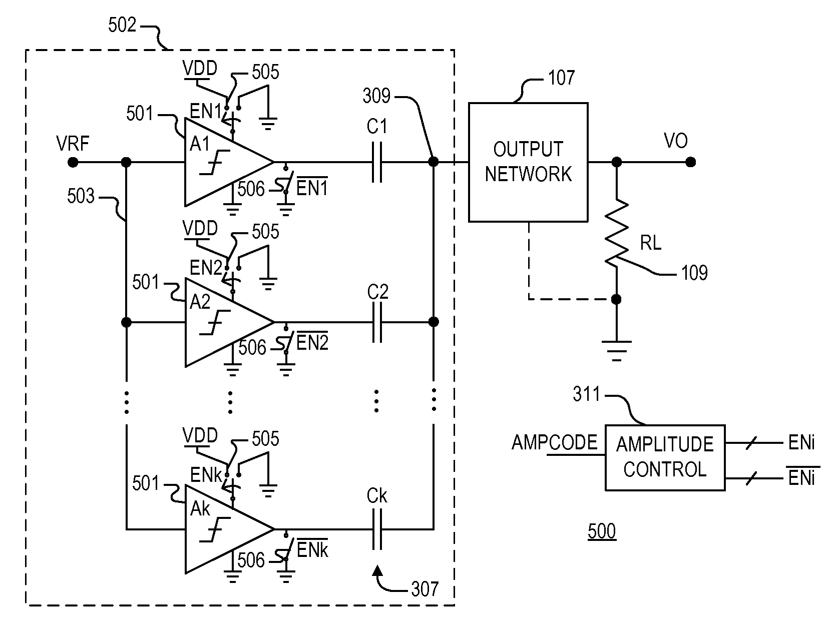
An amplitude control system including one or more multi-element array power amplifiers (MEA-PA), each MEA-PA including multiple amplifiers, multiple capacitors, and multiple enable circuits. Each amplifier has an input coupled to a common input node and an output coupled to a corresponding one of multiple intermediate nodes. Each capacitor has a first end coupled to an output node and a second end coupled to a corresponding intermediate node. The enable circuits are collectively controlled by an amplitude control value, and each is operative to enable or disable a corresponding amplifier. The enable circuits may be dynamically controlled to modulate amplitude. A coupling circuit may be provided to couple an intermediate node to a reference node when a corresponding amplifier is disabled to adjust a coupling ratio. Each amplifier, when enabled, may receive one of multiple supply reference voltages. The capacitors may have equal capacitance or may be binary-weighted.

Description

CROSS-REFERENCE TO RELATED APPLICATIONS[0001]This application claims the benefit of U.S. Provisional Application Ser. No. 61 / 390,792, filed on Oct. 7, 2010 which is herein incorporated by reference in its entirety for all intents and purposes.BACKGROUND OF THE INVENTION[0002]1. Field of the Invention[0003]The present invention relates generally to amplitude control in communication systems, and more specifically, to a modulation system and method to improve the overall efficiency when controlling amplitude of RF signals having a non-constant envelope.[0004]2. Description of the Related Art[0005]Radio Frequency (RF) signals having a non-constant envelope (NCE) are common in several widely deployed wireless and wired or coaxial cable protocols such as 802.11 / WiFi, Bluetooth EDR (Enhanced Data Rate), 3GPP-LTE (3rd Generation Partnership Protocol—Long Term Evolution), WCDMA (Wideband Code Division Multiple Access), HSDPA / HSUPA (High Speed Downlink Packet Access / High Speed Uplink Packet ...

Claims


Application Information

Patent Timeline
Patent Type & Authority Patents(United States)
IPC IPC(8): H04B1/10H03G11/00
CPCH03F3/72H04B1/0475H04B2001/0408H03G11/002H03F3/24
Inventor COOK, BENJAMIN W.
Owner APPLE INC
Learn More