Hydrogen producing apparatus, method of operating hydrogen producing apparatus and fuel cell power generating system

a technology of hydrogen producing apparatus and hydrogen gas, which is applied in the direction of sustainable manufacturing/processing, separation processes, instruments, etc., can solve the problems of insufficient supply of hydrogen gas, a fuel necessary for power generation, as a general infrastructure, and achieve the effect of reducing the amount of raw materials, ensuring stability, and increasing the flow rate of raw materials to be supplied to the odorizing component removal section

Active Publication Date: 2013-05-07
PANASONIC CORP
View PDF28 Cites 2 Cited by
  • Summary
  • Abstract
  • Description
  • Claims
  • Application Information

AI Technical Summary

Benefits of technology

[0052]According to the present invention, even immediately after the odorizing component removing section or the adsorbing agent contained in the odorizing component removing section (odorizing component removing member) is exchanged or even immediately after the adsorbing agent is regenerated, the hydrogen generation apparatus can be stably driven. The starting time period of the hydrogen generation apparatus after the exchange or regeneration can be shortened as compared with the starting time period in the conventional art.
[0053]In addition, during the driving after the exchange or regeneration, the flow rate of the raw material to be supplied to the odorizing component removing section may be increased. Owing to this, the decrease of the amount of the raw material to be supplied from the odorizing component removing section to the reformer can be suppressed. Therefore, the steam-to-carbon ratio in the reformer can be kept at an appropriate value. The decrease of the generation amount of the hydrogen-containing gas due to the exchange of the odorizing component removing member or the regeneration of the adsorbing agent can be suppressed.

Problems solved by technology

A supply system of hydrogen gas, which is a fuel necessary for power generation, is not sufficiently provided as a general infrastructure.
However, especially an odorizer component contained in the odorant such as a sulfur compound may poison a catalyst used in the reformer.

Method used


Image

  • Hydrogen producing apparatus, method of operating hydrogen producing apparatus and fuel cell power generating system
  • Hydrogen producing apparatus, method of operating hydrogen producing apparatus and fuel cell power generating system
  • Hydrogen producing apparatus, method of operating hydrogen producing apparatus and fuel cell power generating system

Examples


embodiment 1

[0092]Hereinafter, a Hydrogen Generation Apparatus in Embodiment 1 according to the present invention will be described.

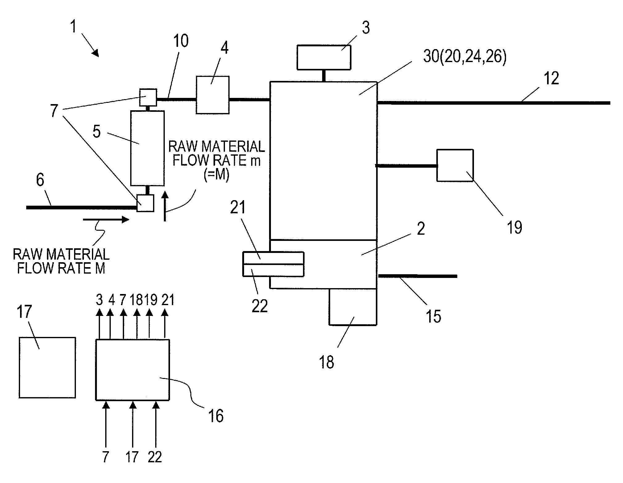
[0093]The hydrogen generation apparatus in this embodiment is an apparatus for generating hydrogen-containing gas using a hydrocarbon-based raw material containing a sulfur component. In order to remove the sulfur component from the raw material, an adsorbing desulfurization section for adsorbing the sulfur component is used. The adsorbing desulfurization section is detachably held in a holding mechanism provided in the hydrogen generation apparatus. When the adsorbing ability on the sulfur component is decreased, the adsorbing desulfurization section is exchanged to a new adsorbing desulfurization section, or only the adsorbing agent (adsorbing desulfurization agent) in the adsorbing desulfurization section is exchanged. Alternatively, the adsorbing desulfurization section may be regenerated. It is preferable that the adsorbing desulfurization section contains an ...

embodiment 2

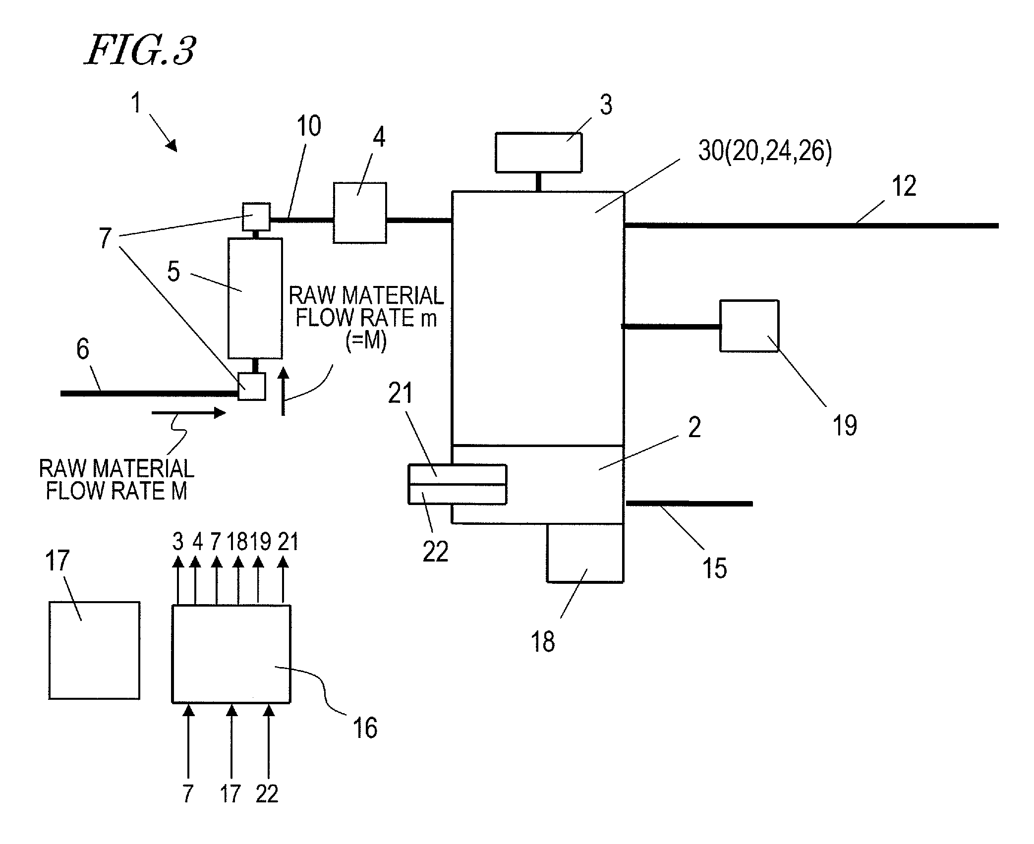
[0150]FIG. 8 is a structural view of a hydrogen generation apparatus in Embodiment 2 according to the present invention. Unlike the hydrogen generation apparatus 1 shown in FIG. 4, the hydrogen generation apparatus in this embodiment is structured such that a part of the raw material supplied from the gas infrastructure line can be sent to the combustor as combustion gas without being passed through the adsorbing desulfurization section.

[0151]In the hydrogen generation apparatus 1 described above with reference to FIG. 4, the raw material which has passed the adsorbing desulfurization section 5 can be sent to the combustor 2 and combusted together with hydrogen off-gas (assist combustion). However, the gas to be combusted in the combustor 2 may contain an odorizing component and does not need to pass the adsorbing desulfurization section 5. Therefore, the hydrogen generation apparatus in this embodiment is structured such that the raw material which has not passed the adsorbing desu...

embodiment 3

[0156]Hereinafter, a hydrogen generation apparatus in Embodiment 3 according to the present invention will be described with reference to the figures.

[0157]FIG. 9 is a block diagram showing a structure of a fuel cell power generation system using the hydrogen generation apparatus in this embodiment. FIG. 10 is a flowchart showing particulars of a control program regarding the odorizing component removing member exchange / regeneration in the hydrogen generation apparatus shown in FIG. 9.

[0158]A fuel cell power generation system 500 shown in FIG. 9 includes a fuel cell 150, a hydrogen generation apparatus 200, and an oxidizing agent gas supply unit 160. The structure of the hydrogen generation apparatus 200 will be described in detail later.

[0159]In this embodiment, the fuel cell 150 is formed of a polymer electrolytic fuel cell. The polymer electrolytic fuel cell is formed as a fuel cell stack by a plurality of cells stacked and tightened. Each cell includes an MEA (not shown) having ...


PUM

PropertyMeasurementUnit
weightaaaaaaaaaa
volumeaaaaaaaaaa
flow rate m0aaaaaaaaaa

Abstract

A hydrogen generation apparatus 1 includes a raw material supply unit 4 for controlling a flow rate of a raw material to be supplied from an external element and containing hydrocarbon and an odorizing component; an odorizing component removing section 5 containing an adsorbing agent for adsorbing the odorizing component contained in the raw material; a combustor 2 for combusting the raw material; a reformer 30 for generating hydrogen-containing gas from the raw material which has passed the odorizing component removing section 5 by a reforming reaction using combustion heat supplied from the combustor 2; and a controller 16 for controlling the raw material supply unit to, during driving after the adsorbing agent or the odorizing component removing section 5 is exchanged or after the adsorbing agent is regenerated, makes the flow rate of the raw material to be supplied from the external element higher than the flow rate during the driving immediately before the exchange or regeneration.

Description

TECHNICAL FIELD[0001]The present invention relates to a hydrogen generation apparatus, a method for driving the same, and a fuel cell power generation system.BACKGROUND ART[0002]Fuel cells capable of power generation at a high efficiency even with a small size is being progressively developed as a key component of a power generation system for a distributed energy supply source. A supply system of hydrogen gas, which is a fuel necessary for power generation, is not sufficiently provided as a general infrastructure. Therefore, a hydrogen generation apparatus including a reformer for generating hydrogen-containing gas using a raw material (hydrocarbon-based gas) supplied from an existing fossil raw material infrastructure such as, for example, city gas, propane gas or the like (the hydrogen generation apparatus is also referred to as the “fuel reforming apparatus”) is installed together with the fuel cell.[0003]Hydrocarbon-based gas such as city gas, propane gas or the like which is s...

Claims


Application Information

Patent Timeline
Patent Type & Authority Patents(United States)
IPC IPC(8): H01M8/06G05D9/00
CPCB01D53/04B01D53/0454C01B3/384C01B3/48B01D2256/24B01D2257/30B01D2257/90C01B2203/0233C01B2203/0283C01B2203/044C01B2203/047C01B2203/066C01B2203/0811C01B2203/0822C01B2203/0827C01B2203/1235C01B2203/1247C01B2203/1258C01B2203/1604C01B2203/1609C01B2203/169H01M8/0618Y02P20/10Y02E60/50
Inventor KANI, YUKIMUNEWAKITA, HIDENOBUFUJIHARA, SEIJIUKAI, KUNIHIRO
Owner PANASONIC CORP
Why Eureka
Try Eureka