High pressure polymerization process

a polymerization process and high pressure technology, applied in chemical/physical/physical-chemical processes, chemical apparatus and processes, chemical/physical/physical-chemical stationary reactors, etc., can solve the problems of polymer deposits affecting the interior walls of the tubes, and achieve the effects of improving plant efficiency, simple and low cost manner, and improving plant efficiency

Active Publication Date: 2013-05-21
EXXONMOBIL CHEM PAT INC
View PDF20 Cites 36 Cited by
  • Summary
  • Abstract
  • Description
  • Claims
  • Application Information

AI Technical Summary

Benefits of technology

[0025]The modifications and improvements of this invention can be applied to an existing plant to increase its efficiency in terms of specific energy consumption and plant capacity. “De-bottlenecking” as used herein means modification of the plant affecting only those parts thereof that limit its capacity in terms of its annual production capacity. De-bottlenecking can create extra capacity at much lower cost than enlarging capacity by constructing a new plant. The de-bottleneck capacity increases may be achieved by increasing conversion and may be associated with an improvement in the specific energy consumption. The same modifications and improvements as are used for de-bottlenecking and increasing plant capacity can also be used to reduce energy consumption by reducing the extent of monomer compression, so reducing the consumption of electricity rather than using the improved efficiency to produce more polymer product.
[0042]Suitably (i) a jet pump means is incorporated to pump the overhead from an intermediate pressure separator into the two-phase cooled reactor effluent stream from the downstream end of the tube for supply to a high pressure separator, (ii) at least part of the overhead recycle of the high pressure separator is passed to the inlet side of the secondary compressor. This permits the plant to be operated such that the balance between the recycle gas mass flow to the primary compressor and that to the secondary compressor can be changed to increase the amount of recycle gas recycled to the secondary compressor. Thus (iii) the proportion of the unreacted monomer recycled to the secondary compressor from the medium pressure separator is increased at the expense of the proportion of the unreacted monomer recycled to the primary compressor from a low pressure separator.

Problems solved by technology

While the bulk of the reactor mixture passing through the tube, sometimes referred to as the “fluidum”, will be in single phase, the external cooling of the tube, especially with a cold coolant fluid, can result in fouling of the interior walls of the tube by polymer deposits.

Method used


Image

  • High pressure polymerization process
  • High pressure polymerization process
  • High pressure polymerization process

Examples


example

General Set Up and Operation of the Plant

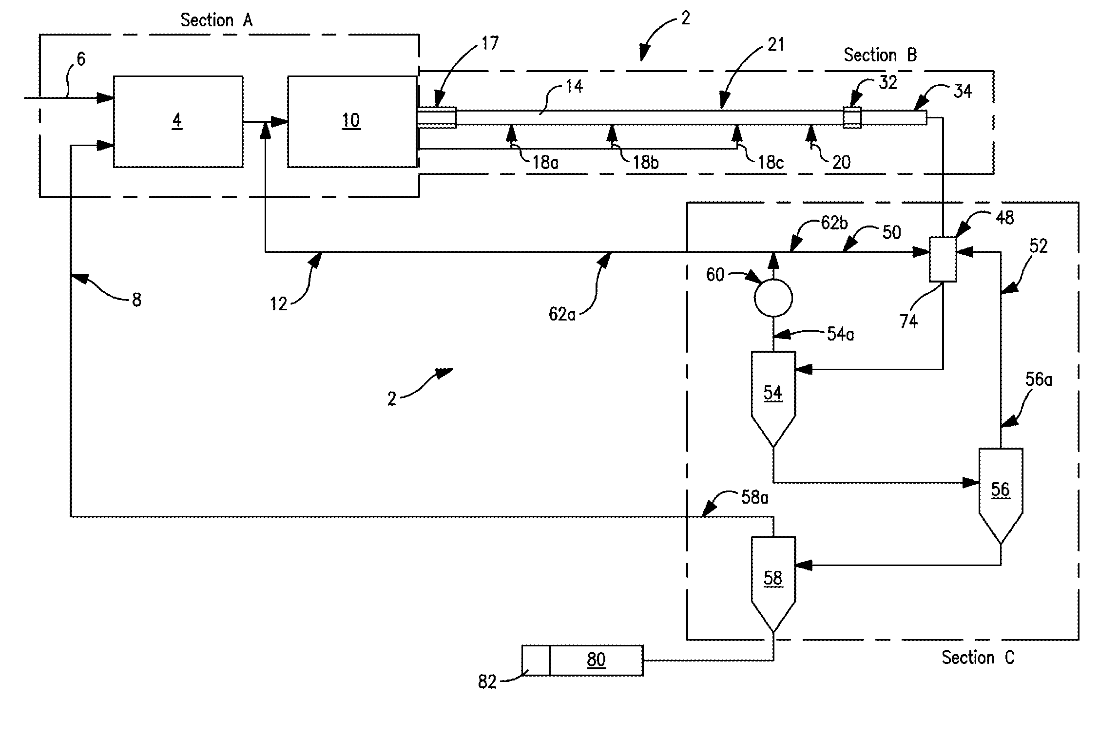
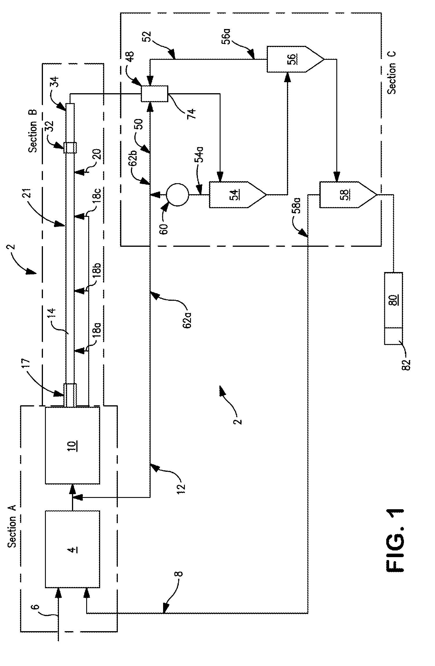
[0083]With reference to FIG. 1, a continuous tubular reactor polymerization plant 2 contains three main sections:[0084]Section A: Compressor equipment and its associated cooling arrangements that raise the pressure of incoming monomer, such as ethylene and optionally one or more comonomers, to the working pressure for polymerization.[0085]Section B: A tubular reactor with its free radical initiator and monomer injection arrangements where the compressed feed is polymerized to the targeted conversion in a single phase condition;[0086]Section C: The separator cascade and associated cooling arrangements that remove the polymer from the reactor effluent and cool and recycle the unreacted components in the effluent back to Section A.

[0087]The invention can be used to increase the plant production capacity. To this end higher conversion is employed. More polymer of suitable quality, of which the most critical are generally the optical properties su...


PUM

PropertyMeasurementUnit
pressureaaaaaaaaaa
pressureaaaaaaaaaa
pressureaaaaaaaaaa

Abstract

The invention relates to high pressure tubular reactor olefin polymerization plants having improved specific energy consumption. The plants may be newly constructed or made by de-bottlenecking an existing plant. The tube of the tubular reactor may have improved arrangements for cooling to increase conversion and optimized polymer-recycle gas separation arrangements using a jet pump for recycling unreacted monomer while permitting haze to be maintained. The improved cooling arrangements include a reduced pressure cooling zone forming the tail end of the tube and / or a shortened heating zone for the front feed and allowing more monomer to be fed as a side feed.

Description

PRIORITY CLAIM[0001]This application is a National Stage Application of International Application No. PCT / US2008 / 087501 filed Dec. 18, 2008, which is hereby incorporated by reference in its entirety.FIELD OF INVENTION[0002]The invention relates to methods for de-bottlenecking and / or reducing the power consumption of continuous tubular olefin polymerization plants and processes using free radical polymerization. The invention relates especially to such plants and processes employing multiple initiator injection points for a plurality of cooled reaction zones. The invention includes the de-bottlenecking by modifying existing, multiple injection point tubular reactor to increase plant capacity and / or reduce the power consumption.BACKGROUND OF INVENTION[0003]Continuous high pressure tubular reactor polymerization plants convert relatively low cost olefin (generally ethylene) monomer feeds into valuable polyolefin product. The polymerization takes place at high temperatures and pressures...

Claims


Application Information

Patent Timeline
Patent Type & Authority Patents(United States)
IPC IPC(8): C08F2/00B01J19/00B01J19/18C08G85/00C08F210/00
CPCB01J19/2415C08F10/02C08F2/01C08F2/00B01J2219/00094B01J2219/00108B01J2219/00254C08F110/02
Inventor LAMMENS, HENRI A.VAN NULAND, TOMGOOSSENS, IVO T.CLAESSENS, ROGER L.VAES, GEERTCLYMANS, PAUL JAN
Owner EXXONMOBIL CHEM PAT INC
Why Eureka
Try Eureka