
Thermal imager using metamaterials

a metamaterial and imager technology, applied in the field of infrared and microwave detector arrays, can solve problems such as unsatisfactory many real-world applications, and achieve the effect of convenient fabrication

Inactive Publication Date: 2013-05-28
TRUSTEES OF BOSTON UNIV +2
View PDF12 Cites 11 Cited by
  • Summary
  • Abstract
  • Description
  • Claims
  • Application Information

AI Technical Summary

Benefits of technology

The solution provides a high-sensitivity, low-cost terahertz radiation detector capable of active imaging with improved spatial resolution and the ability to penetrate opaque materials, suitable for safety and security applications, while operating at room temperature and reducing the complexity of fabrication.

Problems solved by technology

While THz-TDS is one of the most powerful experimental techniques to investigate terahertz science and technology and the associated potential applications, it is not ideal for many real-world applications primarily because of the low-average power and interferometric-like gated detection which necessitates precision alignment.

Method used


Image

  • Thermal imager using metamaterials
  • Thermal imager using metamaterials
  • Thermal imager using metamaterials

Examples


first embodiment

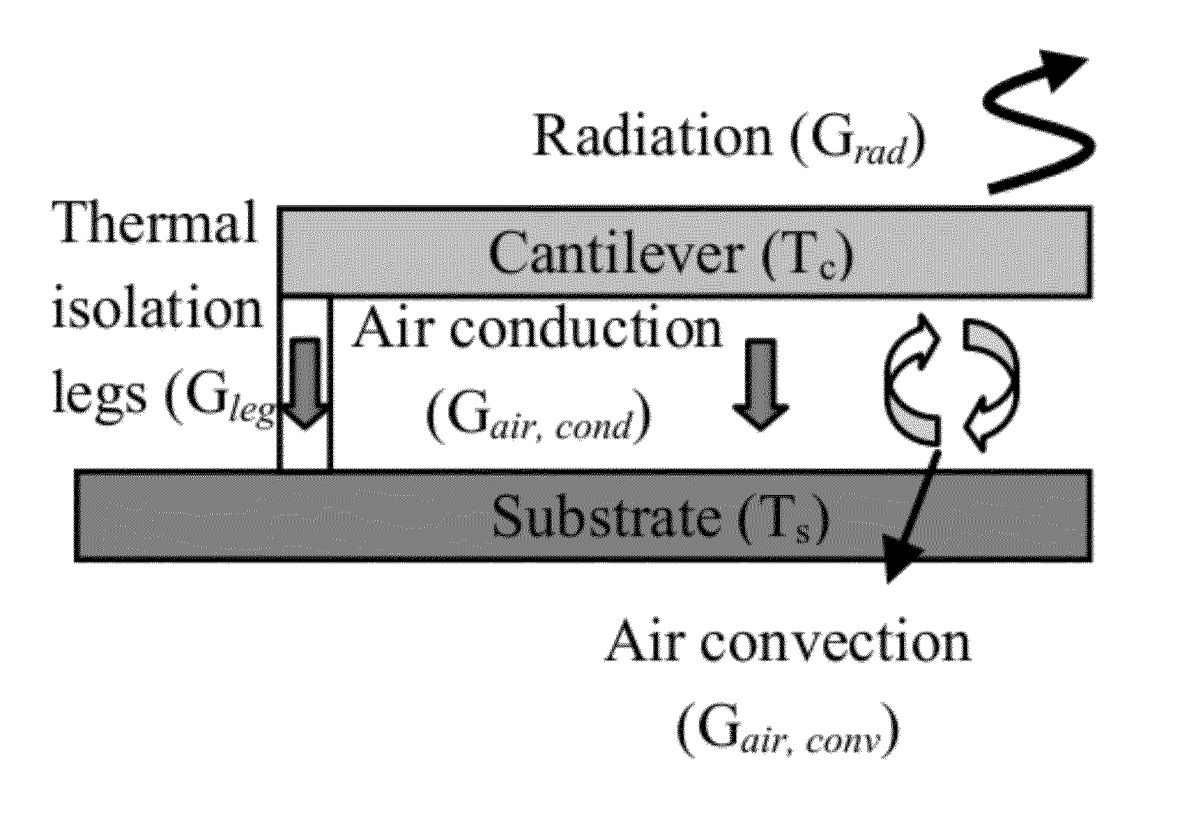
[0014]In the invention, there is provided an apparatus for detecting terahertz radiation at room temperature. The apparatus includes a substrate and a detection structure. The detection structure include (a) an optically reflective surface, and (b) a radiation absorption pad having formed thereon a split-ring resonator. The SRR has a characteristic dimension and an electrical resonance frequency that corresponds to a wavelength of the terahertz radiation that is greater than the characteristic dimension. The detection structure is coupled to the substrate by a flexible cantilever having two types of folded legs. First, the cantilever has a plurality of actuation legs that flex when heated, and are formed from two materials having substantially different coefficients of thermal expansion. Second, the cantilever has a plurality of thermal isolation legs having substantially lower thermal conductivity than the actuation legs.

[0015]The substrate may be a silicon (Si) wafer or a gallium ...

second embodiment

[0016]In the invention, there is provided a method of imaging an object. The method includes illuminating the object with terahertz radiation having a wavelength and absorbing, in a detector, a portion of the terahertz radiation that has interacted with the object. The detector includes a plurality of pixels that move when heated, each pixel having formed thereon a split-ring resonator. At least one of the split-ring resonators has a characteristic dimension that is less than the wavelength of the terahertz radiation and an electrical resonance frequency that corresponds to the wavelength of the terahertz radiation. Absorption of the portion of radiation causes the at least one split-ring resonator to generate sufficient heat to cause movement of the pixel on which it is formed.

[0017]The wavelength of the terahertz radiation detected may be between 30 μm and 3000 μm. The characteristic dimension of the split-ring resonator is between 5 μm and 500 μm. The detector may also include a ...


PUM


Abstract

An apparatus and method are disclosed for detecting terahertz radiation at room temperature. A detecting pixel includes a sub-wavelength split-ring resonator, and is mechanically coupled to (but thermally decoupled from) a substrate via a cantilever formed from two materials that have a significant mismatch in their thermal expansion coefficients. Incident radiation causes the split-ring resonator to resonate, thereby generating heat that is transferred to the cantilever, causing the cantilever to flex. An optical readout system includes a secondary light source, such as a laser, that shines on a reflective surface on the pixel, whereby a photodiode detects the reflected light and permits calculation of a relative deflection of the pixel in the nanometer range. An exemplary detector has a noise equivalent power rating of approximately 60 pW / √Hz.

Description

CROSS-REFERENCE TO RELATED APPLICATION[0001]This application claims the benefit of U.S. Provisional Application No. 61 / 389,625, filed Oct. 4, 2010, the contents of which are incorporated herein by reference in their entirety.STATEMENT REGARDING FEDERALLY SPONSORED RESEARCH OR DEVELOPMENT[0002]This invention was made with Government support under Contract No. HR0011-08-1-0044 awarded by the Defense Advanced Research Projects Agency, and Contract No. ECCS-0802036 awarded by the National Science Foundation. The Government has certain rights in the invention.TECHNICAL FIELD[0003]The present invention relates to an infrared and microwave detector array, and more particularly to a terahertz (THz) detector array having a plurality of independently responsive detectors (pixels).BACKGROUND ART[0004]The terahertz (THz) region of the electromagnetic spectrum extends from 100 GHz to 10 THz (where 1 THz corresponds to a wavelength of 300 microns and photon energy of 4.1 meV). This region, altern...

Claims


Application Information

Patent Timeline
Patent Type & Authority Patents(United States)
IPC IPC(8): G01J5/02
CPCG01J3/42G01J5/0853H01L27/1446H01L27/14649G01J5/40
Inventor AVERITT, RICHARDZHANG, XINTAO, HUSTRIKWERDA, ANDREWPADILLA, WILLIE J.SHANER, ERIC
Owner TRUSTEES OF BOSTON UNIV
Learn More