Inductively coupled plasma flood gun using an immersed low inductance FR coil and multicusp magnetic arrangement

a plasma flood and inductive coupling technology, applied in the direction of irradiation devices, electric discharge lamps, nuclear engineering, etc., can solve the problems of permanent damage, significant drawback of metal contamination, and gradual consumption of tungsten filaments

Active Publication Date: 2013-06-25
VARIAN SEMICON EQUIP ASSOC INC
View PDF38 Cites 10 Cited by
  • Summary
  • Abstract
  • Description
  • Claims
  • Application Information

AI Technical Summary

Problems solved by technology

The resulting positive potentials can create strong electric fields in some miniature structures, causing permanent damage.
One significant drawback is that of metal contamination.
During operation, the tungsten filament is gradually consumed and tungsten atoms may contaminate the ion implantation system as well as the process wafers.
Metal electrodes or other metal components placed inside the plasma chamber may cause similar contaminations.
Although the contamination problem might be alleviated by constructing a plasma chamber completely out of a dielectric material, such a solution may not be desirable because the nonconductive inner surface increases plasma potential and consequently affects the energy of the emitted electrons.
In comparison, excessively energetic electrons can escape from the beam and not arrive at the wafer.
Also, excessively energetic electrons, if they arrive at the wafer, can lead to net negative charging on the wafer surface.
This can result in the build-up of excess negative charge on the wafer surface where the degree to which such a negative electrostatic charge can accumulate on the wafer surface is related to the energy of the electrons arriving at the wafer.
A further challenge in designing a PFG is to make it compact enough to fit into a predefined space reserved for an existing PFG without requiring substantial modifications to existing ion implantation systems.
It is often economically unfeasible to modify a mature ion implantation system just to accommodate a new PFG.

Method used


Image

  • Inductively coupled plasma flood gun using an immersed low inductance FR coil and multicusp magnetic arrangement
  • Inductively coupled plasma flood gun using an immersed low inductance FR coil and multicusp magnetic arrangement
  • Inductively coupled plasma flood gun using an immersed low inductance FR coil and multicusp magnetic arrangement

Examples


Embodiment Construction

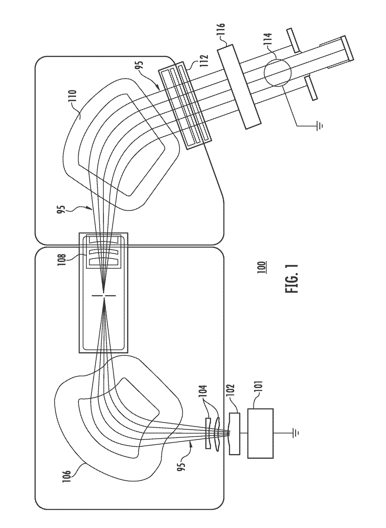
[0018]Ion implanters are widely used in semiconductor manufacturing to selectively alter conductivity of materials. In a typical ion implanter, ions generated from an ion source are directed through a series of beam-line components that may include one or more analyzing magnets and a plurality of electrodes. The beam-line components select desired ion species, filter out contaminant species and ions having undesirable energies, and adjust ion beam quality at a target wafer. Suitably shaped electrodes may modify the energy and the shape of an ion beam.

[0019]An exemplary high current ion implanter tool 100 is generally shown in FIG. 1 and includes an ion source chamber 102, and a series of beam line components that direct the ion beam to a wafer or substrate. These components are housed in a vacuum environment and configured to provide ion dose levels with high or low energy implantation based on the desired implant profile. In particular, implanter 100 includes an ion source chamber ...


PUM


Abstract

A device is disclosed for providing an inductively coupled radio frequency plasma flood gun. In one particular exemplary embodiment, the device is a plasma flood gun in an ion implantation system. The plasma flood gun may comprise a plasma chamber having one or more apertures; a gas source capable of supplying at least one gaseous substance to the plasma chamber; a single-turn coil disposed within the plasma chamber, and a power source coupled to the coil for inductively coupling radio frequency electrical power to excite the at least one gaseous substance in the plasma chamber to generate a plasma. The inner surface of the plasma chamber may be free of metal-containing material and the plasma may not be exposed to any metal-containing component within the plasma chamber. The plasma chamber may include a plurality of magnets for controlling the plasma. An exit aperture may be provided in the plasma chamber to enable negatively charged particles of the resulting plasma to engage an ion beam that is part of the associated ion implantation system. In one embodiment, magnets are disposed on opposite sides of the aperture and are used to manipulate the electrons of the plasma.

Description

BACKGROUND OF THE INVENTION[0001]1. Field of the Invention[0002]Embodiments of the invention relate to the field of ion implantation of semiconductor structures. More particularly, the present invention relates to a plasma flood gun having an immersed RF coil and offset multicusp aperture for generating and directing a low energy plasma into contact with an ion beam.[0003]2. Discussion of Related Art[0004]Ion implantation is a process used to dope impurity ions into a substrate such as, for example, a semiconductor wafer. Generally, an ion beam is directed from an ion source chamber toward a substrate. Different feed gases are supplied to the ion source chamber to obtain plasma used to form ion beams having particular dopant characteristics. For example, from the feed gasses PH3, BF3, or AsH3, various atomic and molecular ions are created within the ion source, and subsequently accelerated and mass selected. The depth of implantation of the generated ions into the substrate is based...

Claims


Application Information

Patent Timeline
Patent Type & Authority Patents(United States)
IPC IPC(8): H05B31/26H01J37/317
CPCH01J37/026H01J37/3171H01J37/32688H01J37/3211H01J2237/03H01J2237/032
Inventor KURUNCZI, PETER F.BENVENISTE, VICTOR M.NAUMOVSKI, OLIVER V.
Owner VARIAN SEMICON EQUIP ASSOC INC
Why Eureka
Try Eureka