Photobioreactor and method for processing polluted air

a photobioreactor and polluted air technology, applied in the field of algae photobioreactors, can solve the problems of increasing the land space requirements of pond-based photobioreactors, inefficient light use, and difficulties in open-channel photobioreactors such as ponds

Active Publication Date: 2013-07-02
PHYCO2 LLC
View PDF13 Cites 5 Cited by
  • Summary
  • Abstract
  • Description
  • Claims
  • Application Information

AI Technical Summary

Benefits of technology

[0029]By one approach, a light source is at least partially positioned inside a portion of the generally vertical helically shaped fluidic pathway. The light source may be a light emitting diode (LED). By one approach, this light source can comprise a plurality of light emitting

Problems solved by technology

In addition to the carbon dioxide emitted from electric power plants, which are some of the biggest producers of such gases, other sources of harmful emissions include manufacturing facilities and diesel power generation plants, to note but a few.
The open channel photobioreactors, such as ponds, have faced difficulties from contamination by hostile species or external pollutants and from the inefficient use of light that illuminates only the top portion of the pond.
This, however, greatly increases land space requirements for pond-based photobioreactors.
In addition, when these ponds use natural sunlight the process is limited by the available hours of sunlight.
Such processing limitations can be important if the photobioreactors are used to process waste gasses from polluting

Method used


Image

  • Photobioreactor and method for processing polluted air
  • Photobioreactor and method for processing polluted air
  • Photobioreactor and method for processing polluted air

Examples


Embodiment Construction

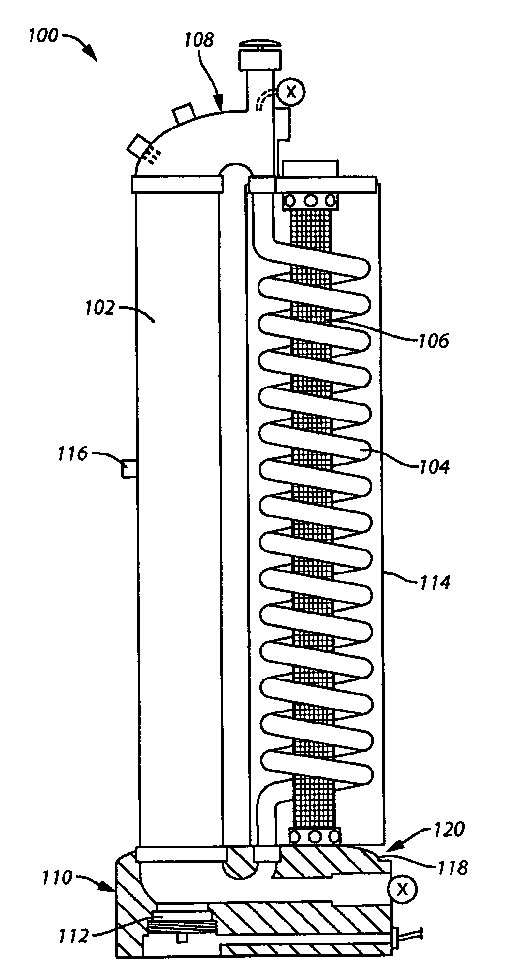
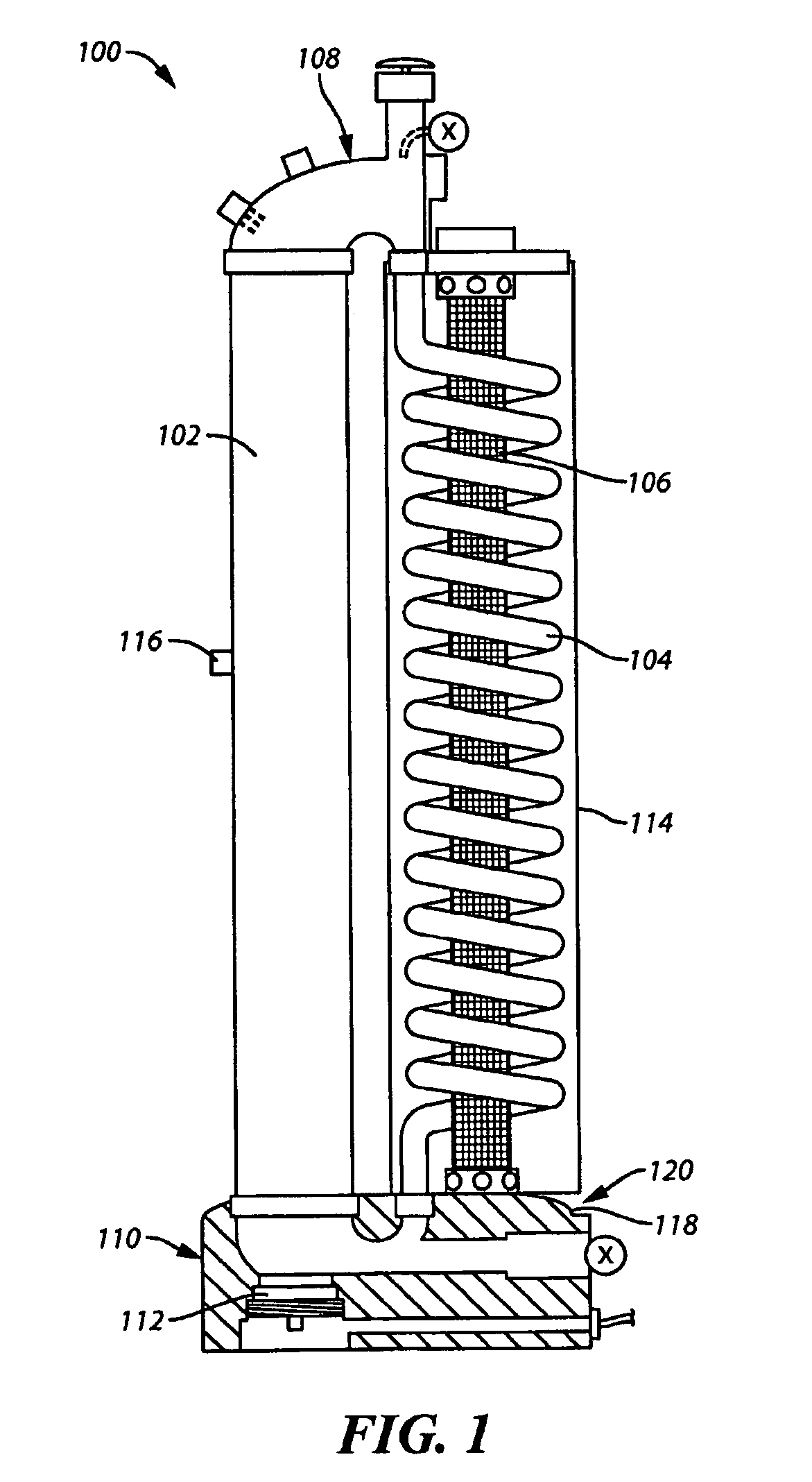
[0031]These and other benefits may become clearer upon making a thorough review and study of the following detailed description. Referring now to the drawings, and in particular to FIG. 1, a photobioreactor 100 for use in treating polluted air and producing biomass is illustrated. The photobioreactor 100 may comprise, at least in part, a generally vertical tube or fluidic pathway 102, a generally vertical helically shaped tube or fluidic pathway 104 having a light source 106 position within the generally vertical helically shaped fluidic pathway 104, a head cap assembly 108, and a base assembly 110. A removable cover 114 may be positioned around the outside of the generally vertical helically shaped fluidic pathway 104 and the light source 106. By one approach, the removable cover 114 includes a reflective interior to reflect the light emitted by the light source 106 back toward the generally vertical helically shaped fluidic pathway 104. In one illustrative example, the light sourc...


PUM


Abstract

A photobioreactor (100) for use in treating polluted air and producing biomass may comprise, at least in part, a generally vertical tube or fluidic pathway (102), a generally vertical helical tube or fluidic pathway (104) having a light source (106) partially positioned within the helical fluidic pathway (104), a head cap assembly (108), and a base assembly (110). In one illustrative example, the light source (106) may be a light emitting diode (LED) or a plurality of light emitting diodes (LEDs). By one approach, a gas diffusion apparatus (112) is located at the base assembly (110) adjacent the generally vertical fluidic pathway (102).

Description

CROSS-REFERENCE TO RELATED APPLICATIONS[0001]This application is a national phase application of International Application No. PCT / US2008 / 052801, filed Aug. 6, 2009, designating the United States and claiming priority to U.S. Patent Application No. 60 / 899,662, filed Feb. 6, 2007, both of which are incorporated by reference herein in their entirety.TECHNICAL FIELD[0002]This invention relates generally to photobioreactors, and more particularly to algal photobioreactors suitable for use in sequestering harmful emissions and producing biomass.BACKGROUND[0003]Bioreactors, including photobioreactors using the principles of photosynthesis, are well known in the art. Photobioreactors use photosynthetic organisms such as algae in a liquid medium along with light energy (whether synthetic light or natural sunlight) and carbon dioxide to create chemical energy from light energy while sequestering carbon dioxide. These systems may have open channels such as ponds or closed channels such as cyl...

Claims


Application Information

Patent Timeline
IPC IPC(8): C12M1/00C12M1/04
CPCB01D53/007B01D53/84B01D2259/802C12M21/02Y02A50/20
Inventor MORGAN, ROBERT
Owner PHYCO2 LLC
Why Eureka
Try Eureka