Bio-oil fractionation and condensation

a technology of biooil and fractionation, applied in biofuels, organic chemistry, fuels, etc., can solve the problems of high oxygen content, large amount of hydrogen consumed during hydrotreatment, corrosion of instruments, etc., and achieve the effects of less usable and valuable oil, poor stability, and poor combustion performan

Active Publication Date: 2013-07-02
IOWA STATE UNIV RES FOUND
View PDF20 Cites 34 Cited by
  • Summary
  • Abstract
  • Description
  • Claims
  • Application Information

AI Technical Summary

Benefits of technology

[0020]The method of fractionating according to the present invention will allow for the selective condensation and collection of bio-oil. Oil recovered by conventional means usually contains water and acid which contributes to its poor stability, corrosion during storage, poor combustion performance, and additional cost to upgrade the bio-oil to transportation fuels. The method of the present invention allows water and acid to be separated from the higher molecular weight organic compounds during the oil recovery process, resulting in a much more usable and valuable oil.

Problems solved by technology

Nonetheless, two main drawbacks of bio-oil limit its usage as high-grade / transportation fuel (Huber et al., “Synthesis of Transportation Fuels from Biomass: Chemistry, Catalysts, and Engineering,”Chem. Rev. 106(9):4044-4098 (2006); Czernik et al., “Overview of Applications of Biomass Fast Pyrolysis Oil,”Energy Fuels 18(2):590-598 (2004); Zhang et al., “Review of Biomass Pyrolysis Oil Properties and Upgrading Research,”Energy Convers. Manage. 48(1):87-92 (2007); and Qasmaa et al., “Fuel Oil Quality of Biomass Pyrolysis Oils—State of the Art for the End User,”Energy Fuels 13(4):914-921 (1999)).
These drawbacks include (1) high acidity (pH of 2-3), which causes the corrosion of instruments, and (2) high oxygen content (35-40 wt.
The existence of carboxylic acids in bio-oil will lead to the consumption of a large amount of hydrogen during hydrotreatment.
Therefore, the common method of distillation (as performed with crude oil) for separation of fractions is not effective.
Previous attempts to optimize these lab-scale multistage condensing systems to fractionate the bio-oil have fared poorly due to the use of this low temperature coolant which causes the high boiling point compounds to congeal and solidify on the walls of the condenser tubes where they are subsequently converted into char which over time leads to char buildup eventual blockage of the condenser tubes.

Method used


Image

  • Bio-oil fractionation and condensation
  • Bio-oil fractionation and condensation
  • Bio-oil fractionation and condensation

Examples


example 1

Typical Test Operation

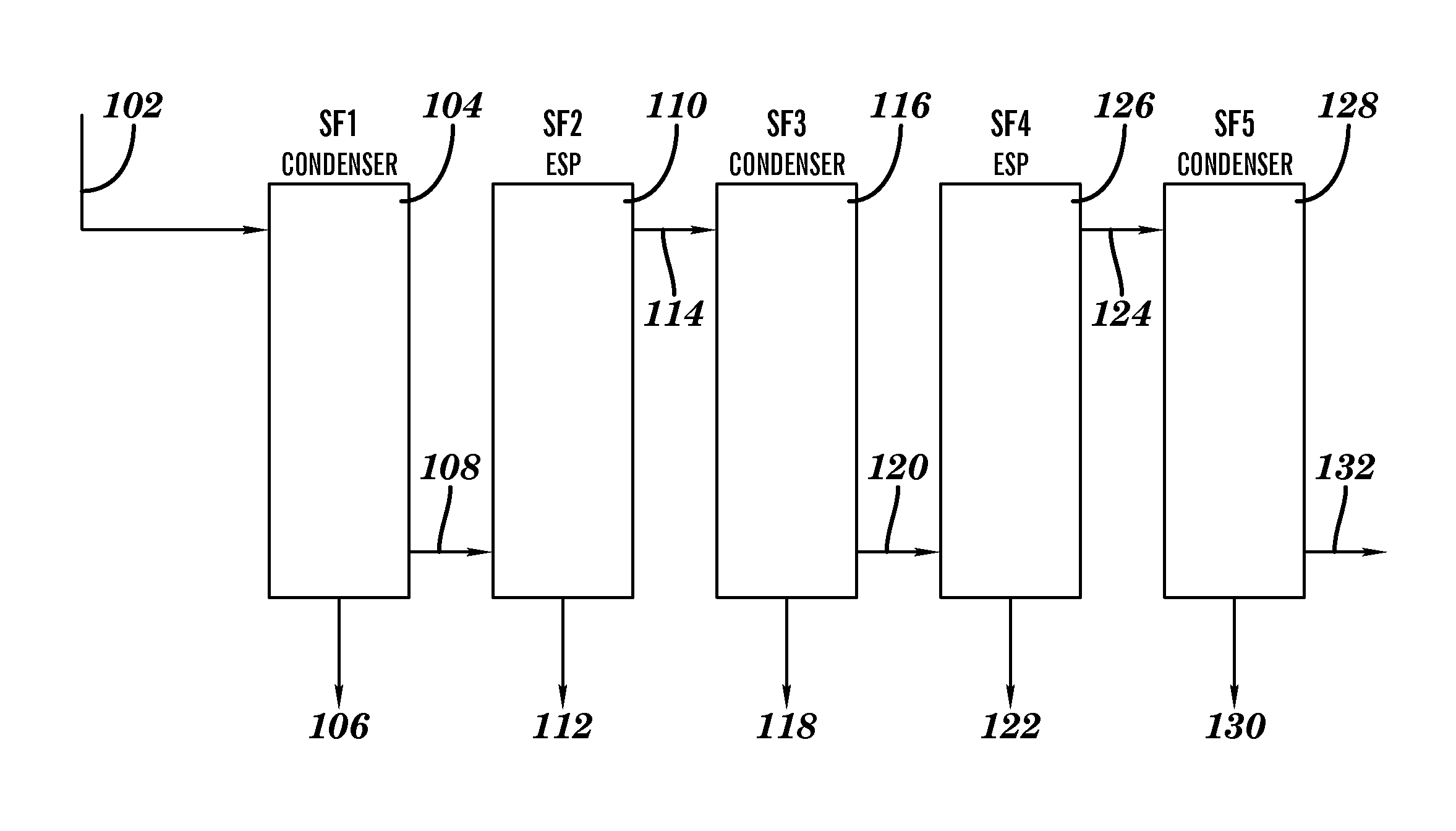
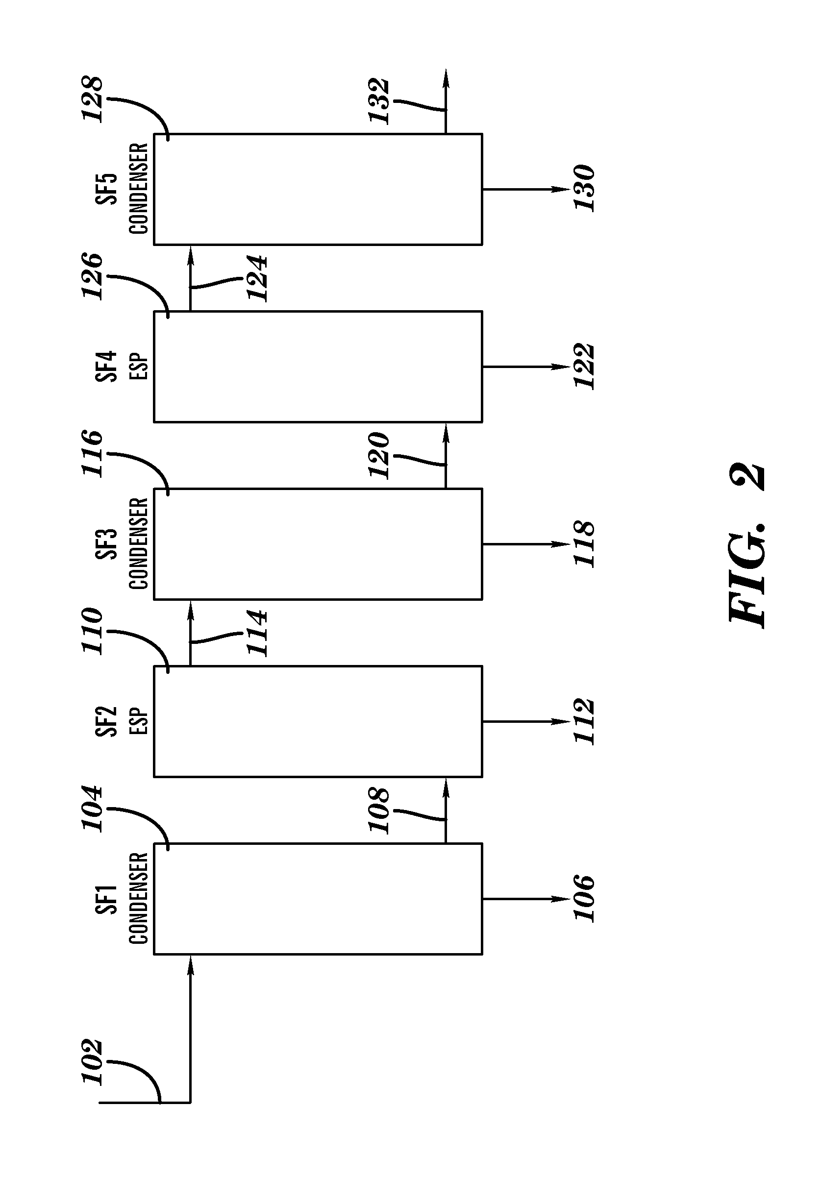
[0093]The bio-oil collection system consists of three bio-oil vapor condensers and one or more electrostatic precipitators (which act as aerosol filters), as described in FIG. 2. Each of these components has been designed to collect a specific fraction of the bio-oil. This document provides a detailed description of the design and operation of the bio-oil collection system, referring specifically to the performance of an 8 kg / h process development unit constructed by Iowa State University at the BECON Facility in Nevada, Iowa.

[0094]Multiple tests have been completed of the bio-oil collection system. Tests have been completed using red oak, corn stover, and switchgrass. For these tests of the bio-oil collection system, the configuration was as follows: condenser 104 (SF1), ESP 110 (SF2), condenser 116 (SF3), ESP 124 (SF4), condenser 128 (SF5). Below is a detailed description of the operation of the bio-oil collection system during a single test.

[0095]Fast pyroly...

example 2

Fractionation of Red Oak

[0098]FIG. 11 is a chart of the weight percentages of the different bio-oil liquid fractions obtained from the red oak feedstock. Fast pyrolysis vapor produces from red oak in the fluid bed reactor entered the condenser 104 at 345° C. After a passage through a cyclonic filtration system to remove char, these bio-oil vapors entered the first condenser tubes. The tubes walls were maintained at a constant temperature of 95° C. This first stage allowed the condensation of 21% of the weight percentage of first liquid fraction. The remaining vapors proceeded through the second stage which was composed of ESP 110. An average temperature of about 102° C. allowed the condensation of a second liquid fraction of 30%. Vapors exited the second stage and entered the third stage at a temperature of 120° C. The tube walls of condenser 116 were maintained at a constant temperature of 66° C. This resulting condensation bio-oil was evaluated at 6% of the third liquid fraction. ...

example 3

Fractionation of Cornstover

[0100]FIG. 12 is a chart of the weight percentages of the different bio-oil liquid fractions obtained from the cornstover feedstock. Cornstover was fluidized in a reactor held at 512° C. The resulting vapors entered condenser 104 in which the tubes walls were maintained at 87° C. A first fraction was collected at this stage in 8% of the first liquid bio-oil fraction. The remaining vapors continued into the ESP 110 where the inlet and outlet temperatures were held, respectively, at 82 and 125° C. This second stage afforded 18% of the second liquid fraction. The non-condensed vapors entered condenser 116 where the tubes walls were held at a constant temperature of 67° C., 4% of the third liquid fraction was obtained from the original cornstover feedstock. ESP 124 allowed the collection of 12% of the fourth liquid fraction. The temperatures between the inlet and outlet of the second ESP were, respectively, 76 and 78° C. The last stage of the fractionation inv...


PUM

PropertyMeasurementUnit
temperatureaaaaaaaaaa
temperaturesaaaaaaaaaa
timeaaaaaaaaaa

Abstract

A method of fractionating bio-oil vapors which involves providing bio-oil vapors comprising bio-oil constituents is described. The bio-oil vapors are cooled in a first stage which comprises a condenser having passages for the bio-oil separated by a heat conducting wall from passages for a coolant. The coolant in the condenser of the first stage is maintained at a substantially constant temperature, set at a temperature in the range of 75 to 100° C., to condense a first liquid fraction of liquefied bio-oil constituents in the condenser of the first stage. The first liquid fraction of liquified bio-oil constituents from the condenser in the first stage is collected. Also described are steps for subsequently recovering further liquid fractions of liquefied bio-oil constituents. Particular compositions of bio-oil condensation products are also described.

Description

[0001]This application claims the benefit of U.S. Provisional Patent Application Ser. No. 61 / 093,045, filed Aug. 29, 2008, which is hereby incorporated by reference in its entirety.[0002]This invention was made with funding received from the Department of Energy under grant DE-FG36-07-G087003 and the United States Department of Agriculture under grant 68-3A75-5-233. The U.S. government has certain rights in this invention.FIELD OF THE INVENTION[0003]The present invention relates to bio-oil fractionation and condensation.BACKGROUND OF THE INVENTION[0004]Biomass, such as forestry and agricultural products and residues, is a major underutilized product in the world. There are several different technologies for converting the biomass to useful energy (e.g., direct burn, co-firing, gasification, and the like) or to biobased products (e.g., fermentation, pyrolysis, and the like), in particular bio-oil. Depending on the type of process used, the final product may have different values and ...

Claims


Application Information

Patent Timeline
Patent Type & Authority Patents(United States)
IPC IPC(8): C07C1/00C10B47/00
CPCC10K1/04C10C5/00C10B53/02Y02E50/14C10G1/02Y02E50/10C10L1/1802
Inventor BROWN, ROBERT C.JONES, SAMUEL T.POLLARD, ANTHONY
Owner IOWA STATE UNIV RES FOUND
Why Eureka
Try Eureka