
Method for producing a PCD compact

a polycrystalline diamond and compact technology, applied in the field of polycrystalline diamond (pcd) materials, can solve the problems of reducing the strength of bonded diamond, limiting the potential industrial applications of this material and the potential fabrication routes that can be used, and reducing the performance of compact at high temperatures. achieve the effect of improving abrasion resistance, reducing the volume of open pores, and facilitating further densification of the pcd structur

Active Publication Date: 2013-07-16
ELEMENT SIX ABRASIVES
View PDF15 Cites 32 Cited by
  • Summary
  • Abstract
  • Description
  • Claims
  • Application Information

AI Technical Summary

Benefits of technology

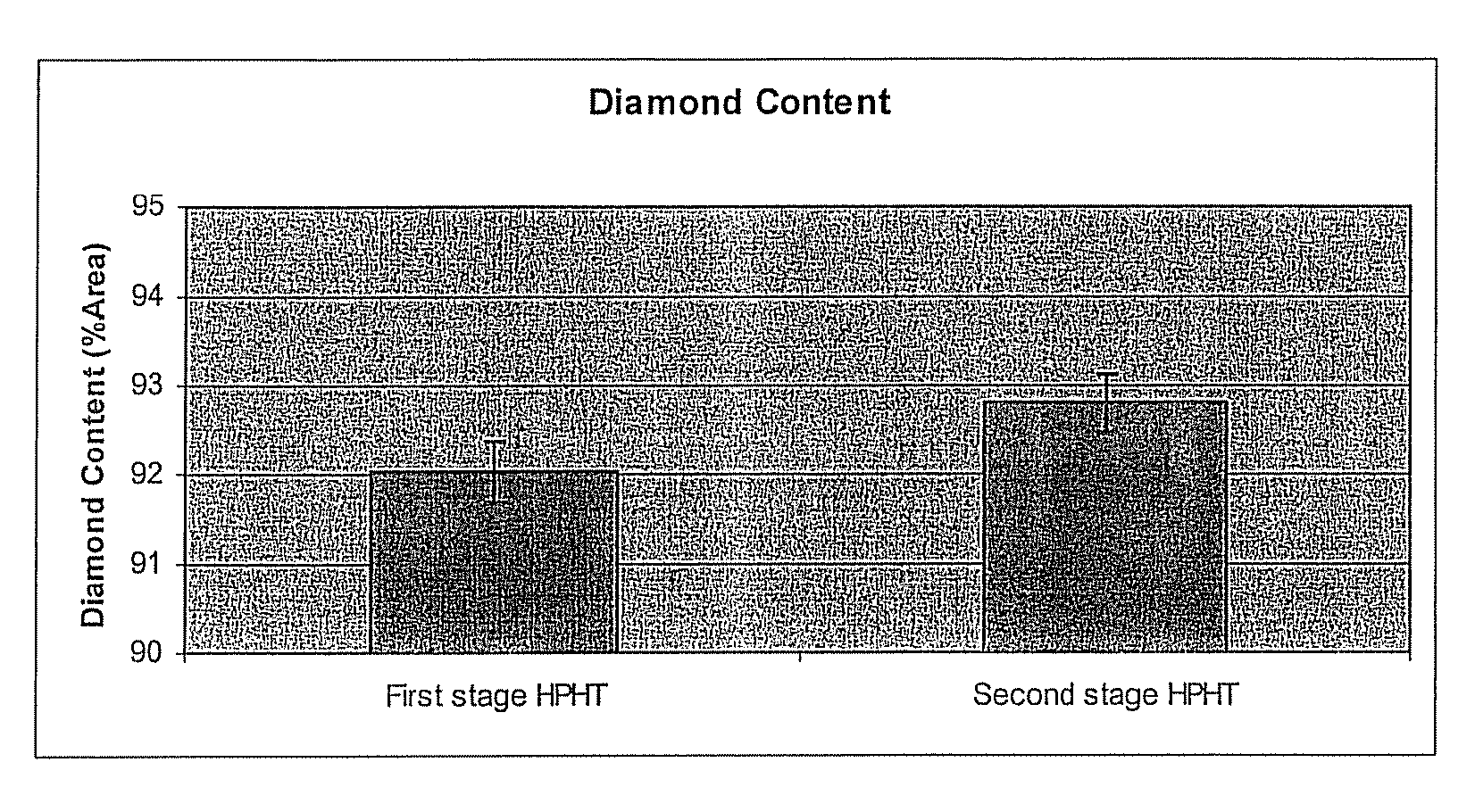
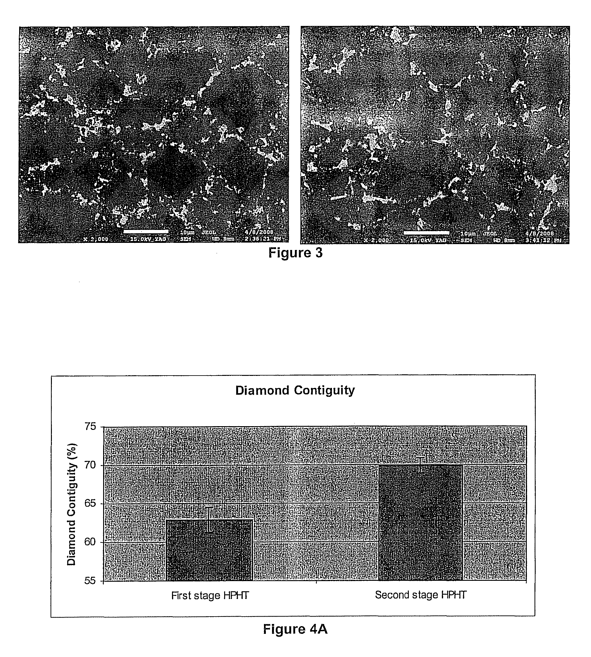
[0038]The PCD table is subjected to a modified HpHT treatment in the bonding step to attach the PCD table to a cemented tungsten carbide substrate. It is carried out by a process in which increased time intervals of cold compaction and hot compaction of the PCD may be used such that there is an increased time for particle rearrangement during plastic deformation to produce a product having a higher diamond contiguity and density. The method of the invention therefore leads to change in the PCD microstructure after the modified HpHT process to produce a product having better abrasion and thermal resistance. This is particular so when the PCD table has a porous microstructure substantially free of second phase material.
[0042]During cold compaction in the initial compaction step the PCD undergoes elastic consolidation as a result of applied pressure without increased temperature. Plastic deformation takes place during hot compaction prior to the bonding agent melting. These compaction mechanisms facilitate further densification of the PCD structure, reducing the volume of the open pores, and hence the volume of re-infiltrating material that subsequently infiltrates and fills the pores. The improvement in the abrasion and thermal resistance is therefore attributed to improved diamond packing and contact. The densification of the PCD structure is particularly apparent when the pores of the porous microstructure of the PCD table are empty, i.e. substantially free of second phase material.

Problems solved by technology

A well-known problem experienced with this type of PCD compact, however, is that the residual presence of solvent / catalyst material in the microstructural interstices has a detrimental effect on the performance of the compact at high temperatures.
This micro-fracturing significantly reduces the strength of the bonded diamond at increased temperatures.
PCD sintered in the presence of a metallic solvent / catalyst, notwithstanding its superior abrasion and strength characteristics, must be kept at temperatures below 700° C. This significantly limits the potential industrial applications for this material and the potential fabrication routes that can be used.
There are several problems that result from this approach to achieving improved thermal stability.
Firstly, these leached PCD pieces with their continuous network of empty pores possess a substantially increased surface area, which can result in increased vulnerability to oxidation (particularly at higher temperatures).
This can then result in reduced strength of the PCD compact at high temperatures, albeit via a different mechanism.
Porous leached PCD compacts of this type also suffer from technical attachment problems, in that they must still be brazed to a carbide substrate prior to use.
This brazing step is technically challenging and often provides a subsequent weak point within the compact tool structure.
It has been observed that compacts generated according to these teachings experiences high internal stresses because of the significant differences in properties between the leached / porous layer and the underlying sintered PCD and carbide substrate.
This is exacerbated by the monolithic nature of the leached compact and often causes cracking at the PCD-substrate interface or through the PCD layer itself during the second attachment HpHT cycle.
Furthermore, the reattachment process itself can be difficult to control such that appreciable re-infiltration of the TSPCD layer does not occur during the second HpHT cycle
Typically, it is extremely difficult and time-consuming to effectively remove the bulk of the metallic binder from the finer-grained and thicker PCD tables required by current applications.
This fine network resists penetration by the leaching agents, such that residual catalyst / solvent often remains behind in the leached compact, compromising its eventual thermal stability.
Furthermore, achieving appreciable leaching depths can take so long as to be commercially unfeasible or require undesirable interventions, such as extreme acid treatments or the drilling of penetration channels into the bulk PCD, for example.
Whilst substantial removal of the catalyst / solvent in this region to a depth of approximately 200-500 μm from the working surface does observably improve the performance of the cutting element in specific applications, certain problems are still experienced.
This masking process is not technically trivial and further limits the range of leaching treatments that can be employed without causing significant damage to the portions of the cutter that must be protected.
There is a further technical limitation inherent in this approach.

Method used


Image

  • Method for producing a PCD compact
  • Method for producing a PCD compact
  • Method for producing a PCD compact

Examples


example

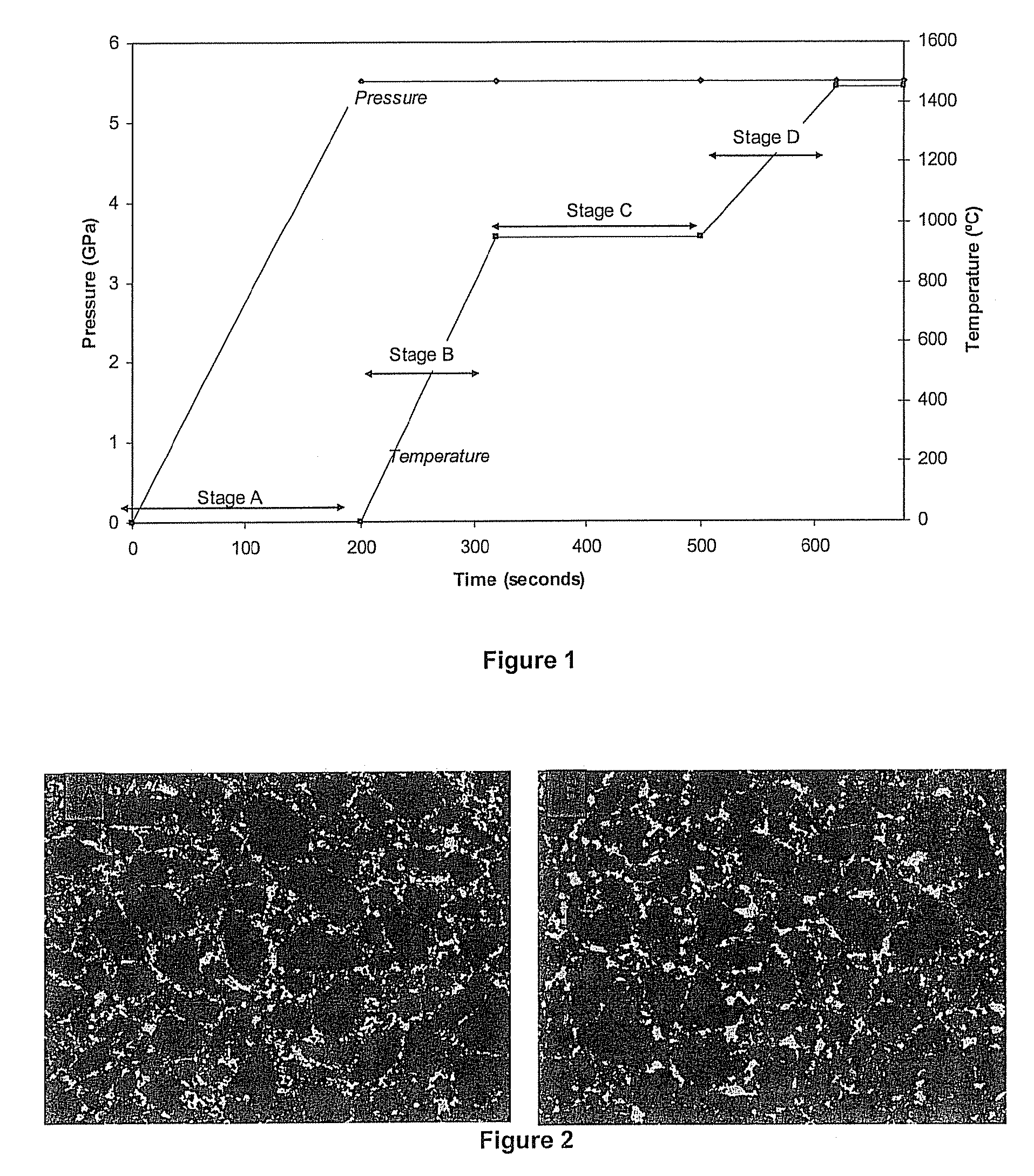
[0068]A sintered PCD table was first formed using a conventional HpHT cycle according to methods well known in the art. A multimodal diamond powder mixture backed with a cemented tungsten carbide substrate was assembled and treated in a vacuum furnace to remove any impurities. This green state product was then subjected to HpHT sintering conditions to produce a standard compact comprising a PCD table bonded to a cemented carbide substrate. A control sample of backed PCD generated using this method was set aside for comparative purposes. The microstructure of this comparative sample was investigated using SEM.

[0069]SEM analysis of the comparative formed PCD (FIGS. 2A and 3A) clearly shows the presence of diamond intergrowth within this PCD table. The dark regions in the micrograph represent the diamond phase, the grey regions represent the binder / catalyst cobalt and the lighter regions represent the tungsten carbide phases. The grey and lighter regions represent the second phase and ...


PUM

PropertyMeasurementUnit
pressureaaaaaaaaaa
pressureaaaaaaaaaa
temperaturesaaaaaaaaaa

Abstract

A method of producing a composite diamond compact comprising a polycrystalline diamond (PCD) compact bonded to a cemented carbide substrate is provided. The method includes the steps of: providing a PCD table, preferably a PCD table with diamond-to-diamond bonding and a porous microstructure in which the pores are empty of second phase material bringing together the PCD table and a cemented carbide substrate in the presence of a bonding agent to form an unbonded assembly; subjecting the unbonded assembly to an initial compaction at a pressure of at least 4.5 GPa and a temperature below the melting point of the bonding agent for a period of at least 150 seconds; and thereafter subjecting the unbonded assembly to a temperature above the melting point of the bonding agent and a pressure of at least 4.5 GPa for a time sufficient for the bonding agent to become molten and bond the PCD table to the substrate to form a composite diamond compact.

Description

[0001]This application is a 371 of PCT / IB2009 / 052344 filed on Jun. 3, 2009, published on Dec. 10, 2009 under publication number WO 2009 / 147629 A and claims priority benefits of British Patent Application Number 0810184.2 filed Jun. 4, 2008, the disclosure of which is incorporated herein by reference.BACKGROUND OF THE INVENTION[0002]This invention relates to the manufacture of polycrystalline diamond (PCD) materials.[0003]Polycrystalline diamond, also known as a diamond abrasive compact, comprises a mass of diamond particles containing a substantial amount of direct diamond-to-diamond bonding. Polycrystalline diamond will generally have a second phase which contains a diamond catalyst / solvent such as cobalt, nickel, iron or an alloy containing one or more such metals.[0004]When diamond particles are combined with a suitable metallic solvent / catalyst, this solvent / catalyst promotes diamond-to-diamond bonding between the diamond grains, resulting in an intergrown or sintered structure....

Claims


Application Information

Patent Timeline
Patent Type & Authority Patents(United States)
IPC IPC(8): E21B10/46E21B10/567
CPCB01J3/065B22F7/062C22C26/00B01J2203/063B01J2203/0655C22C2204/00
Inventor SITHEBE, HUMPHREY SAMKELO LUNGISANI
Owner ELEMENT SIX ABRASIVES
Learn More