Motor and electric device using same

a technology of electric devices and motors, applied in the direction of windings insulation materials, dynamo-electric machines, supports/encloses/casings, etc., can solve the problems of abnormal sound, deterioration of conductivity of conductive lubricant agents, and corrosion of electric bearings, so as to reduce the shaft voltage of bearings and reduce the impedance

Active Publication Date: 2013-08-06
PANASONIC CORP
View PDF16 Cites 6 Cited by
  • Summary
  • Abstract
  • Description
  • Claims
  • Application Information

AI Technical Summary

Benefits of technology

[0022]With the above configuration, the two brackets are electrically connected to cause both the brackets to have the same potential, a potential difference between the inner ring and the outer ring of one bearing and a potential difference between the inner ring and the outer ring of the other bearing are approximated to each other or equal to each other. The impedance adjusting member is arranged between the stator iron core and the brackets connected to each other to make it possible to adjust an impedance on a stator side. More specifically, as described above, in the conventional configuration, an impedance on rotor side is low, and the impedance on the stator side is high. In contrast to this, in the configuration of the present invention, on the stator side, both the brackets have the same potentials, the impedance adjusting member is arranged to decrease the impedance on the stator side, and the impedance on the stator side is matched with the impedance on the rotor side having a low impedance. For this reason, the potential of the bearing inner ring can be made almost equal to the potential of the outer ring of the corresponding bearing, the shaft voltages of the bearings can be lowered. In this manner, since a potential difference between the inner ring and the outer ring of each of the two bearings fixed with the conductive brackets can be lowered, the bearing can be suppressed from being electrically corroded by a high-frequency wave caused by PWM or the like while securing the fixing strength of the bearing.

Problems solved by technology

When the shaft voltage reaches a breakdown voltage of an oil film in the bearing, a minute electric current flows in the bearing to cause electric corrosion in the bearing.
When the electric corrosion progresses, a wavelike abrasion phenomenon may occur on a bearing inner ring, a bearing outer ring, or bearing balls to generate abnormal sound, and the abnormal sound is one main factor of drawback in the motor.
However, a conductive lubricant agent is deteriorated in conductivity with elapsed time, and lacks in sliding reliability.
However, this method disadvantageously requires brush abrasion powder or a space.
This method highly effectively suppresses electric corrosion but disadvantageously has high cost.
The method cannot be employed in a general-purpose motor.
Since a potential on the bearing inner ring side and a potential on the bearing outer ring side are high and low, respectively, an imbalanced state occurs, and a high shaft voltage is generated.
The high shaft voltage may cause electric corrosion in the bearing.
However, the molding material is a resin that is not strong enough to fix the bearing and has poor dimensional accuracy for resin molding, and creeping in the bearing disadvantageously easily occurs.
However, the conventional method as described in Patent Document 1 has the following problem.
More specifically, since the conventional method is a method using short-circuiting, an impedance cannot be adjusted, and a shaft voltage may increase depending on a magnet material or a structure of a rotor.
Even though electric corrosion does not occur in one bearing, electric corrosion may disadvantageously occur in the other bearing.
Therefore, it is difficult to employ a conventional configuration in which a stator iron core or the like of a motor is electrically connected to the earth and to solve the problem by a configuration added with the conventional technique because still another problem is posed in terms of specifications and characteristics of a motor.Patent Document 1: Unexamined Japanese Patent Publication No. 2007-159302

Method used


Image

  • Motor and electric device using same
  • Motor and electric device using same
  • Motor and electric device using same

Examples


embodiment 1

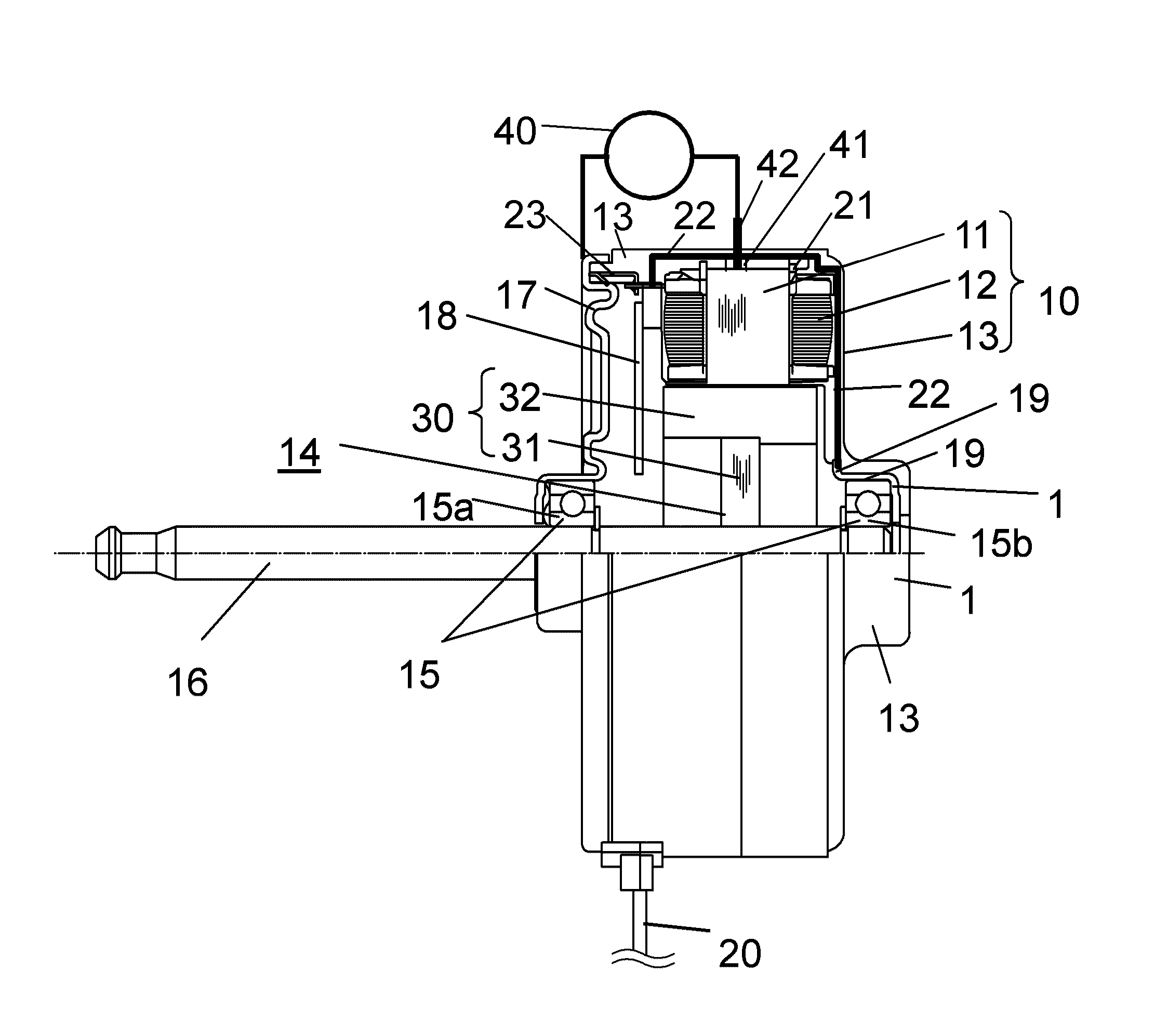
[0039]FIG. 1 is a structural diagram showing a cross section of a brushless motor according to Embodiment 1 of the present invention. In the present embodiment, an example of a brushless motor that is a motor to drive a blowing fan mounted for an air conditioner serving as an electric device will be described. In the present embodiment, an example of an inner rotor type brushless motor in which a rotor is rotatably arranged on an inner circumference side of a stator will be described.

[0040]In FIG. 1, on stator iron core 11, stator winding 12 is wound on insulator 21 serving as a resin to insulate stator iron core 11. Stator iron core 11 is molded together with another fixing member with insulating resin 13 serving as a molding material. In the present embodiment, the members are integrally molded to configure stator 10 having a generally cylindrical shape as an outer shape.

[0041]Inside stator 10, rotor 14 is inserted via a gap. Rotor 14 has disk-like rotating body 30 including rotor...

example 1

[0060]In the configuration shown in FIG. 1, dielectric elements having capacitances of 10 pF, 50 pF, 100 pF, 150 pF, and 300 pF were connected in series between bracket 17 and connection pin 42 as capacitors 40 to measure shaft voltages. As the dielectric element, an air variable capacitor (variable capacitor) the capacitance of which can be arbitrarily adjusted was used.

[0061]As magnet 32 held by rotor 14, a ferrite resin magnet was used. As bearing 15, 608 available from Minebea Co., Ltd. (grease having a consistency of 239 was used) was used.

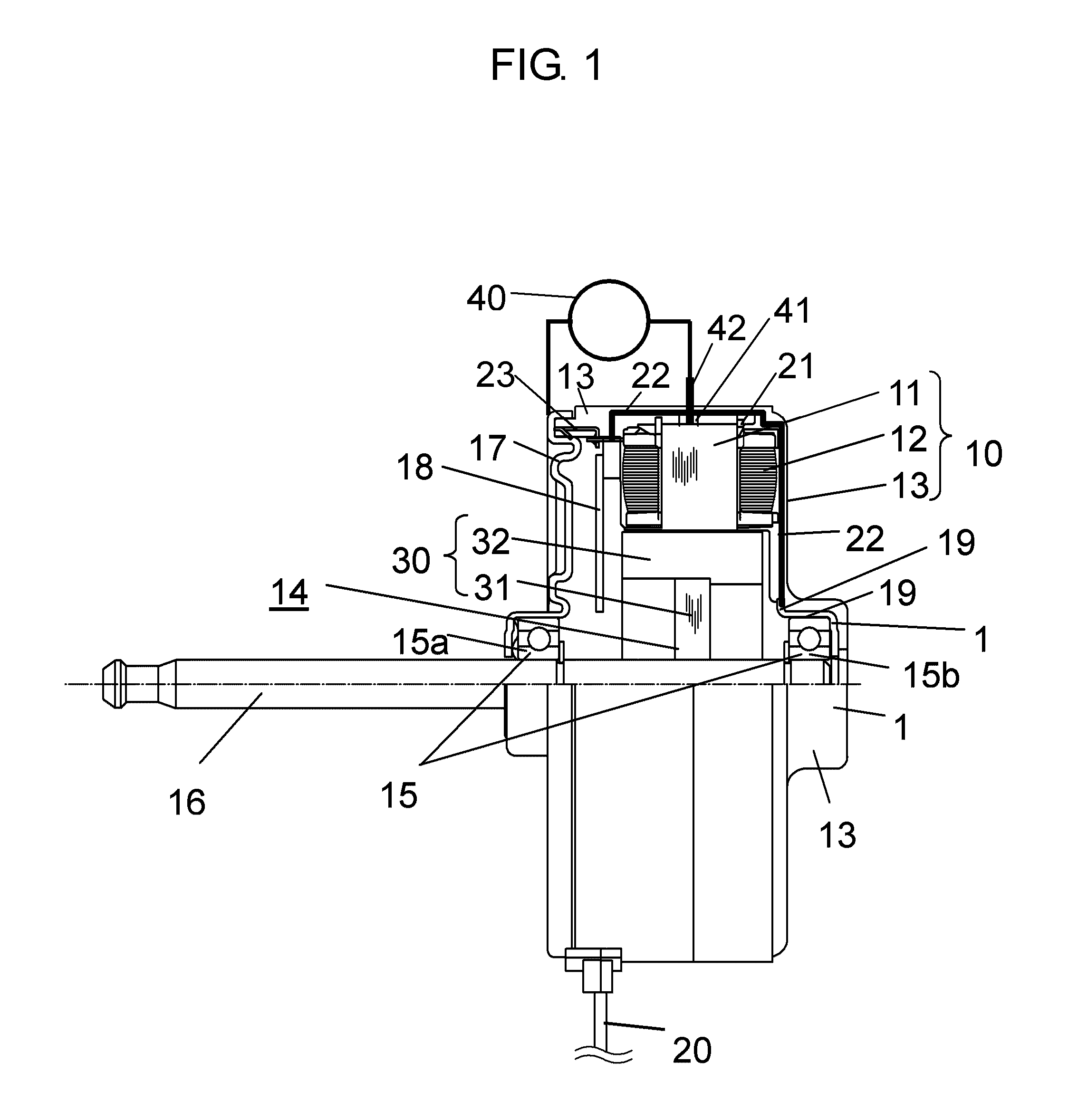
[0062]FIG. 2 is a diagram showing a method of measuring a shaft voltage in Example 1. A DC stabilized power supply was used in a shaft voltage measuring state. The measurement was executed under the same operating conditions in which power supply voltage Vdc of a stator winding was set to 391 V, power supply voltage Vcc of the control circuit was set to 15 V, and a rotating speed was set to 1000 r / min. The rotating speed was adjusted by contr...

example 2

[0078]In Example 2, evaluations were performed while changing the types of magnets 32 held by rotor 14. The evaluations were performed by using a ferrite resin magnet and a neodymium magnet as magnets 32. In the configuration as shown in FIG. 1, when rotor 14 holds a ferrite resin magnet, a dielectric element having capacitance of 100 pF was connected in series between bracket 17 and connection pin 42 as capacitor 40. When rotor 14 holds a neodymium magnet, a dielectric element having capacitance of 150 pF was connected in series between bracket 17 and connection pin 42 as capacitor 40. The brushless motors of the two types were manufactured and evaluated by the same method as that in Example 1.

[0079]In order to check an electric corrosion suppressing effect in the above specification, the brushless motors were prepared, and the electric corrosion suppressing effects were checked by an electric corrosion endurance test.

[0080]The electric corrosion endurance test was executed under t...


PUM


Abstract

A motor includes: a stator including a stator iron core on which a winding is wound; a rotor including a rotating body that holds a magnet in a circumferential direction to face the stator and a shaft that fastens the rotating body to penetrate a center of the rotating body; a bearing that supports the shaft; and two conductive brackets that fix the bearing. The two brackets are electrically connected to each other, and a capacitor serving as an impedance adjusting member that adjusts impedances between the stator iron core and the electrically connected two brackets is arranged.

Description

[0001]This application is a 371 application of PCT / JP2009 / 006782 having an international filing date of Dec. 11, 2009, which claims priority to JP2008-316377 filed on Dec. 12, 2008, the entire contents of which are incorporated herein by reference.TECHNICAL FIELD[0002]The present invention relates to motors and electric devices using the same and, more particularly, to a motor that is improved to suppress electric corrosion from occurring in a bearing and an electric device using the same.BACKGROUND ART[0003]In recent years, a motor has often employed a method in which a motor is driven by an inverter using a pulse width modulation system (to be arbitrarily referred to as a PWM system hereinafter). In the inverter driving of the PWM system, since a neutral-point potential of a winding is not zero, a potential difference (to be referred to as a shaft voltage hereinafter) is generated between an outer ring and an inner ring of a bearing. The shaft voltage includes a high-frequency com...

Claims


Application Information

Patent Timeline
Patent Type & Authority Patents(United States)
IPC IPC(8): H02K3/30
CPCH02K11/0089H02K5/1732H02K11/40
Inventor MIZUKAMI, HIROFUMIWATANABE, AKIHIKOHASEGAWA, TAKEHIKOKADO, HARUHIKO
Owner PANASONIC CORP
Why Eureka
Try Eureka