Optical signal transfer in a semiconductor device by using monolithic opto-electronic components

a monolithic opto-electronic and semiconductor technology, applied in the direction of optics, optical elements, instruments, etc., can solve the problems of significant restrictions imposed by complex integrated circuits on the final obtained device performance, and achieve the effects of enhancing overall device performance, enhancing overall process complexity, and superior design flexibility

Active Publication Date: 2013-08-13
GLOBALFOUNDRIES US INC
View PDF8 Cites 10 Cited by
  • Summary
  • Abstract
  • Description
  • Claims
  • Application Information

AI Technical Summary

Benefits of technology

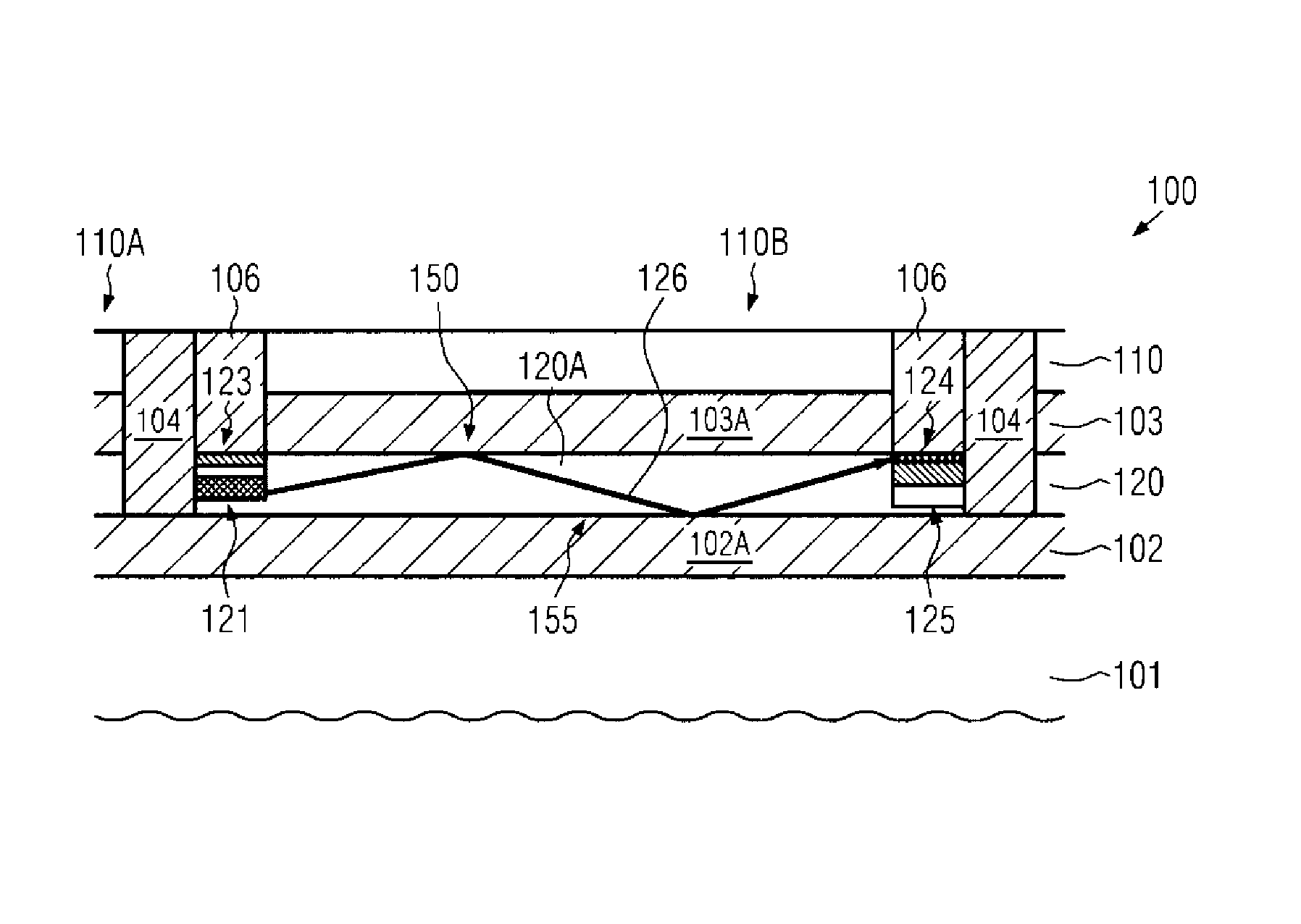
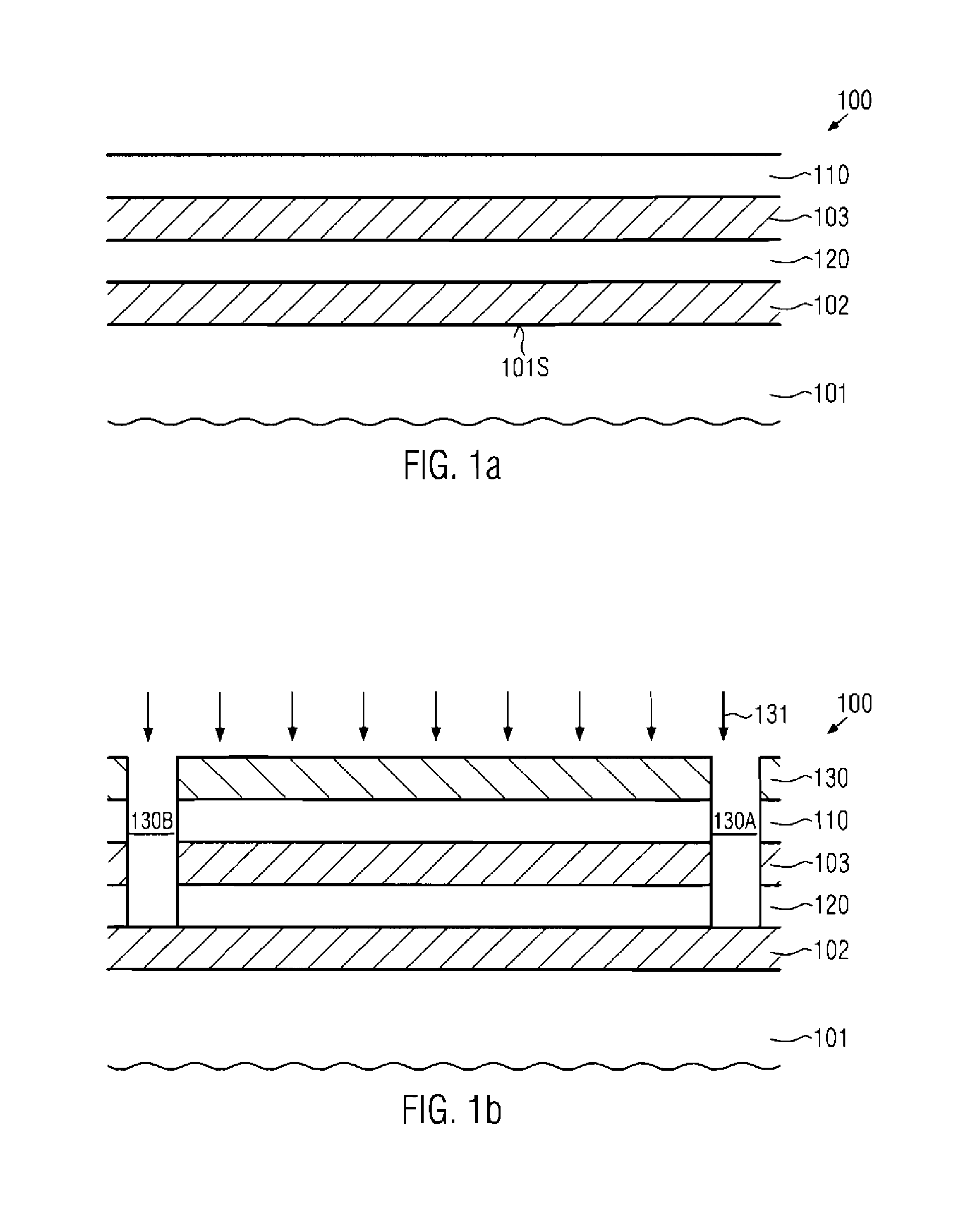
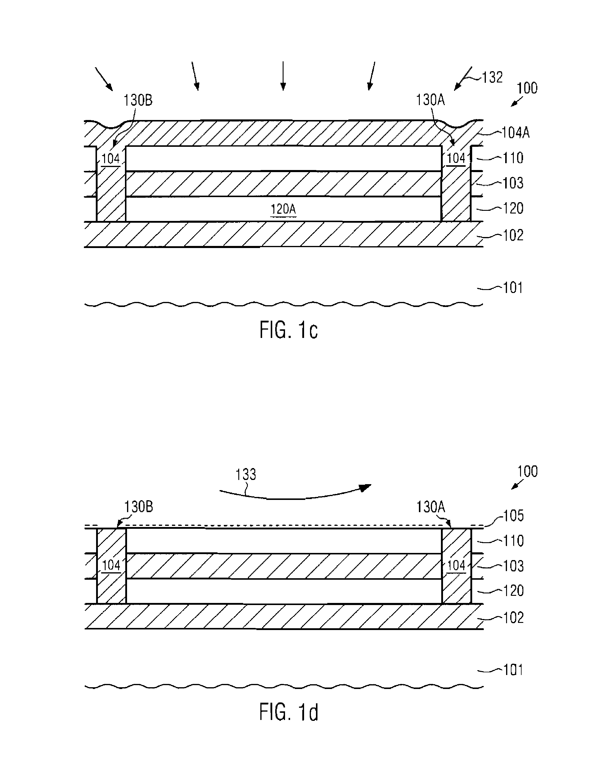
[0010]Generally the present disclosure provides semiconductor devices and manufacturing techniques in which silicon-based opto-electronic components, i.e., light-emitting elements and light-receiving elements, may be used for a device-internal signal exchange and, in some illustrative embodiments, for the chip-internal signal exchange. As previously explained, the increasing complexity of metallization systems and interconnect systems of complex integrated circuits impose significant restrictions on the finally obtained device performance, for instance with respect to the thermal budget, operating speed, adaptation of circuit portions of different supply voltage and the like. For this reason, the present disclosure provides semiconductor devices in which optical signal transfer capabilities may be provided within integrated circuit devices or even within a single semiconductor chip by using monolithically implemented opto-electronic components. For this purpose, silicon-based light-emitting devices, for instance based on dislocation loops and any other intentionally generated modifications of the silicon base material, may be advantageously implemented during the process sequence for forming circuit elements of a complex circuit, such as a microprocessor and the like, in order to implement the functionality of converting electrical signals into optical signals and visa versa. Furthermore, appropriate optical communication paths, such as waveguides and the like, may be implemented in order to operatively connect different circuit elements via the optical signal transfer. In some illustrative aspects, an optical communication path may be provided in the form of a semiconductor-based waveguide, which may be formed on the basis of manufacturing techniques that may not unduly contribute to an increased overall process complexity. In other illustrative aspects disclosed herein, the optical signal exchange capabilities based on monolithically implemented opto-electronic components may be used for an inter-chip communication of a three-dimensional integrated circuit device, thereby providing superior design flexibility and also enhanced overall device performance. Thus, an efficient signal exchange may be accomplished on the basis of monolithically implemented opto-electronic components, thereby relaxing any constraints with respect to the thermal budget, while at the same time allowing enhanced design flexibility. Furthermore, a superior overall device performance may be obtained due to superior signal propagation speeds on the basis of an electrically decoupled communication path.

Problems solved by technology

As previously explained, the increasing complexity of metallization systems and interconnect systems of complex integrated circuits impose significant restrictions on the finally obtained device performance, for instance with respect to the thermal budget, operating speed, adaptation of circuit portions of different supply voltage and the like.

Method used


Image

  • Optical signal transfer in a semiconductor device by using monolithic opto-electronic components
  • Optical signal transfer in a semiconductor device by using monolithic opto-electronic components
  • Optical signal transfer in a semiconductor device by using monolithic opto-electronic components

Examples


Embodiment Construction

[0019]Various illustrative embodiments of the invention are described below. In the interest of clarity, not all features of an actual implementation are described in this specification. It will of course be appreciated that in the development of any such actual embodiment, numerous implementation-specific decisions must be made to achieve the developers' specific goals, such as compliance with system-related and business-related constraints, which will vary from one implementation to another. Moreover, it will be appreciated that such a development effort might be complex and time-consuming, but would nevertheless be a routine undertaking for those of ordinary skill in the art having the benefit of this disclosure.

[0020]The present subject matter will now be described with reference to the attached figures. Various structures, systems and devices are schematically depicted in the drawings for purposes of explanation only and so as to not obscure the present disclosure with details ...


PUM


Abstract

In a semiconductor device, optical signal transfer capabilities are implemented on the basis of silicon-based monolithic opto-electronic components in combination with an appropriate waveguide. Thus, in complex circuitries, such as microprocessors and the like, superior performance may be obtained in terms of signal propagation delay, while at the same time thermal requirements may be less critical.

Description

BACKGROUND OF THE INVENTION[0001]1. Field of the Invention[0002]The present disclosure generally relates to the field of fabricating integrated circuits, and, more particularly, to interconnect structures for signal exchange in complex integrated circuits.[0003]2. Description of the Related Art[0004]In modern integrated circuits, a very high number of individual circuit elements, such as field effect transistors in the form of CMOS, NMOS, PMOS elements, resistors, capacitors and the like, are formed on a single chip area. Typically, feature sizes of these circuit elements are continuously decreased with the introduction of every new circuit generation, to provide currently available integrated circuits formed by volume production techniques with critical dimensions of 50 nm or less and having an improved degree of performance in terms of speed and / or power consumption. A reduction in size of transistors is an important aspect in steadily improving device performance of complex integ...

Claims


Application Information

Patent Timeline
Patent Type & Authority Patents(United States)
IPC IPC(8): H01L27/14
CPCG02B6/12004G02B6/43H01L31/173H01L27/15
Inventor GRIEBENOW, UWEBEYER, SVENSHEIPER, THILOHOENTSCHEL, JAN
Owner GLOBALFOUNDRIES US INC
Why Eureka
Try Eureka