UV irradiance monitoring in semiconductor processing using a temperature dependent signal

a technology of temperature dependent signal and irradiance monitoring, which is applied in the direction of semiconductor/solid-state device testing/measurement, nuclear engineering, therapy, etc., can solve the problem that the internal stress level cannot be changed to a tensile stress, the process parameters may be difficult to control, and the requirements of sophisticated integrated circuits are no longer suitable, etc. problem, to achieve the effect of high degree of flexibility, superior monitoring capabilities, and efficient processing

Active Publication Date: 2013-08-27
TAIWAN SEMICON MFG CO LTD
View PDF12 Cites 0 Cited by
  • Summary
  • Abstract
  • Description
  • Claims
  • Application Information

AI Technical Summary

Benefits of technology

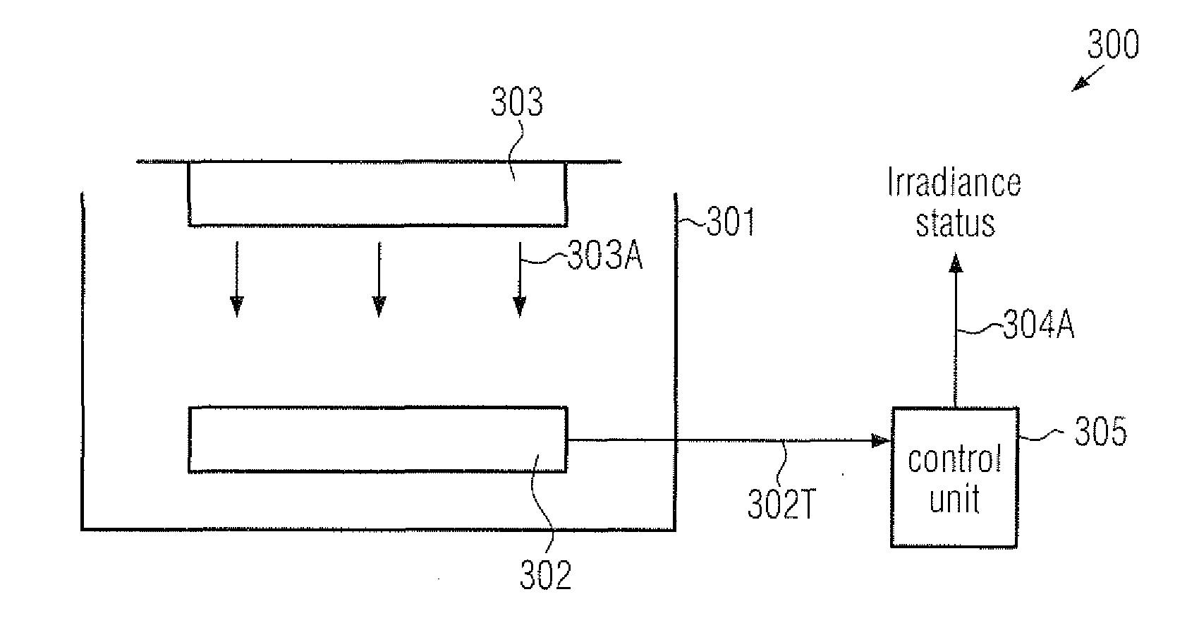
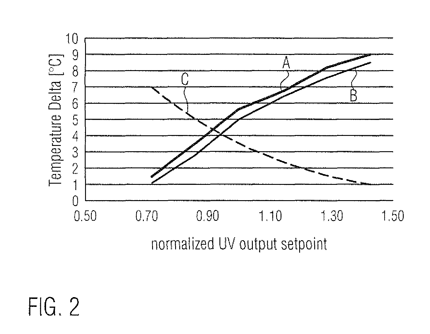
[0013]Generally, the present disclosure provides UV treatment tools and methods in which materials during the semiconductor processing may be efficiently processed on the basis of UV radiation, while additionally providing superior monitoring capabilities for assessing the momentary irradiance of a radiation source used during the UV treatment. To this end, an appropriate monitor signal may be obtained, which may be correlated to the temperature of one or more hardware components within the process chamber which are affected by the UV radiation emitted by the radiation source. It has been recognized that the thermal conditions within the process chamber may be strongly related to the momentary irradiance of the radiation source so that a monitor signal may be obtained that is correlated to the process temperature or a temperature of a hardware component in the process chamber. Consequently, the temperature under consideration and thus the signal indicative of this temperature may represent an average of the irradiance effects of the entire wavelength range of the radiation source so that the monitor signal may be sensitive to a variation of irradiance of the whole wavelength range, or a portion thereof, wherein, at the same time, a spatial average may also be obtained, thereby avoiding the assessment of the momentary irradiance on the basis of a very restricted scan area, as may typically be the case in conventional UV process tools including a specific UV sensor. Thus, in some illustrative embodiments disclosed herein, the monitor signal may represent a temperature signal of any appropriate hardware component, such as a chamber wall, a heater unit, a substrate, if present in the process chamber, and the like, so that a high degree of flexibility is provided in order to assess the irradiance at any desired point in time. For example, the monitoring may be performed without a substrate or may be performed during the processing of a substrate, thereby also providing the possibility of monitoring the irradiance on the basis of individual process runs, which may thus provide a high degree of process uniformity. In other illustrative embodiments disclosed herein, the monitor signal may be obtained on the basis of hardware components, such as a control unit configured to operate a heater unit, which may thus provide information on the thermal effect of the radiation to be monitored for a constant temperature process scenario. In other illustrative aspects disclosed herein, the monitor signal may be efficiently used to control the radiation source during the UV treatment in order to maintain the momentary irradiance within predefined limits, which may even enable a run-to-run process control due to the fast response to a change of the thermal conditions and thus the effective irradiance.

Problems solved by technology

Well-established metallization systems are based on aluminum and silicon dioxide as conductive materials and interlayer dielectric materials, which, however, may no longer be appropriate for meeting the requirements of sophisticated integrated circuits.
For instance, it has been recognized that the molecular structure of a silicon nitride material may be changed upon exposure to UV radiation, which may result in a removal of hydrogen, which in turn may result in a shift of an internal stress level towards a tensile stress.
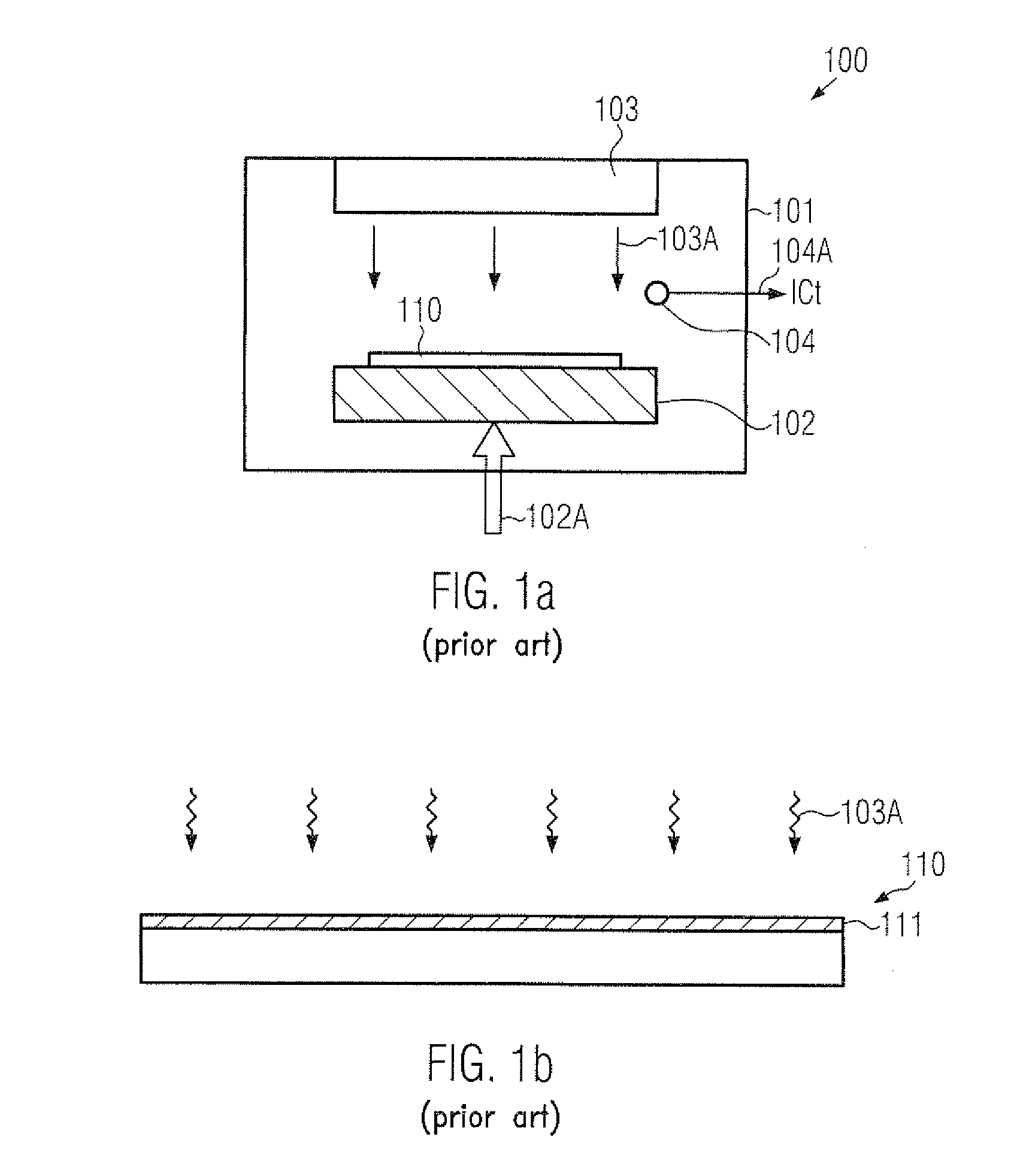
However, these process parameters may be difficult to control, as will be explained with reference to FIGS. 1a and 1b.
Thus, the dielectric constant of the resulting dielectric material may strongly depend on the overall process parameters, which in turn may significantly affect the electrical performance of the metallization systems and thus of the semiconductor devices.
Moreover, currently available UV sensors may also suffer from a pronounced variability so that the long term stability of the UV measurement system itself may not be guaranteed, thereby making the currently available monitor systems for UV radiation tools based on the sensor 104 less than desirable, in particular for sophisticated manufacturing techniques requiring a high uniformity of the involved processes.
In this case, however, in addition to processing the substrate 110, a further metrology process has to be performed, which may thus not allow a fast response to the tool 100 since, typically, at least a time interval of one hour or more may be required until the measurement result is obtained.
In this time interval, the tool 100 may not be available or may be operated with a high risk of producing non-acceptable process results.

Method used


Image

  • UV irradiance monitoring in semiconductor processing using a temperature dependent signal
  • UV irradiance monitoring in semiconductor processing using a temperature dependent signal
  • UV irradiance monitoring in semiconductor processing using a temperature dependent signal

Examples


Embodiment Construction

[0025]Various illustrative embodiments of the invention are described below. In the interest of clarity, not all features of an actual implementation are described in this specification. It will of course be appreciated that in the development of any such actual embodiment, numerous implementation-specific decisions must be made to achieve the developers' specific goals, such as compliance with system-related and business-related constraints, which will vary from one implementation to another. Moreover, it will be appreciated that such a development effort might be complex and time-consuming, but would nevertheless be a routine undertaking for those of ordinary skill in the art having the benefit of this disclosure.

[0026]The present subject matter will now be described with reference to the attached figures. Various structures, systems and devices are schematically depicted in the drawings for purposes of explanation only and so as to not obscure the present disclosure with details ...


PUM


Abstract

In a UV process tool for semiconductor processing, a temperature-dependent signal may be used as a monitor signal for determining the momentary irradiance of the UV radiation source. Consequently, a fast and reliable monitoring and / or controlling of the irradiance of UV process tools may be accomplished.

Description

BACKGROUND OF THE INVENTION[0001]1. Field of the Invention[0002]Generally, the present disclosure relates to the fabrication of integrated circuits, and, more particularly, to techniques and systems for performing a UV (ultraviolet) treatment.[0003]2. Description of the Related Art[0004]Semiconductor devices and generally any type of microstructure devices are typically formed on specific substrates made of any appropriate material. During the very complex manufacturing sequence, a plurality of material layers are typically formed on the substrate and are subsequently treated, for instance, by etching one or more materials, implanting specific impurities, such as dopant species and the like, in order to obtain individual components having the desired characteristics. For example, semiconductive materials, insulating materials, highly conductive materials, such as metals and the like, are formed and may be patterned, for instance on the basis of sophisticated lithography techniques, ...

Claims


Application Information

Patent Timeline
Patent Type & Authority Patents(United States)
IPC IPC(8): H01L21/66
CPCH01L21/3105H01L21/67115H01L21/67248
Inventor MAYER, ULRICHSCHEPERS, THORSTEN
Owner TAIWAN SEMICON MFG CO LTD
Why Eureka
Try Eureka