Swept mode-hopping laser system, methods, and devices for frequency-domain optical coherence tomography

a laser system and frequency-domain technology, applied in the field of light sources, can solve the problems of tunable long-cavity lasers, lasers suffer from severe trade-offs between scanning speed and coherence length, and tunable long-cavity lasers also tend to be bulky, etc., to achieve short intensity fluctuations, high repetition rates, and fast sweep speeds

Active Publication Date: 2013-11-12
LIGHTLAB IMAGING
View PDF87 Cites 73 Cited by
  • Summary
  • Abstract
  • Description
  • Claims
  • Application Information

AI Technical Summary

Benefits of technology

[0008]Preferred laser embodiments are described that produce short transition times (< about 1 ns) between modes at typical sweep rates. As a result, these short transition times permit brief intensity fluctuations at the laser output. These intensity fluctuations occur as the wavelength of the laser is tuned. In turn, these fluctuations serve as synchronization pulses for acquisition of FD-OCT interference signals. Furthermore, if the cavity length of the laser is chosen such that the mode-hop frequency of the laser equals the Nyquist sampling frequency of the OCT system, or an exact multiple thereof, nearly artifact-free OCT imaging can be achieved using such lasers.

Problems solved by technology

Unfortunately, tunable long-cavity lasers also have several significant disadvantages as FD-OCT light sources.
Because of the long photon residence time inside the laser cavity, these lasers suffer from a severe trade-off between scanning speed and coherence length.
Tunable long-cavity lasers also tend to be bulky and difficult to mass produce at low cost.

Method used


Image

  • Swept mode-hopping laser system, methods, and devices for frequency-domain optical coherence tomography
  • Swept mode-hopping laser system, methods, and devices for frequency-domain optical coherence tomography
  • Swept mode-hopping laser system, methods, and devices for frequency-domain optical coherence tomography

Examples


embodiment 10

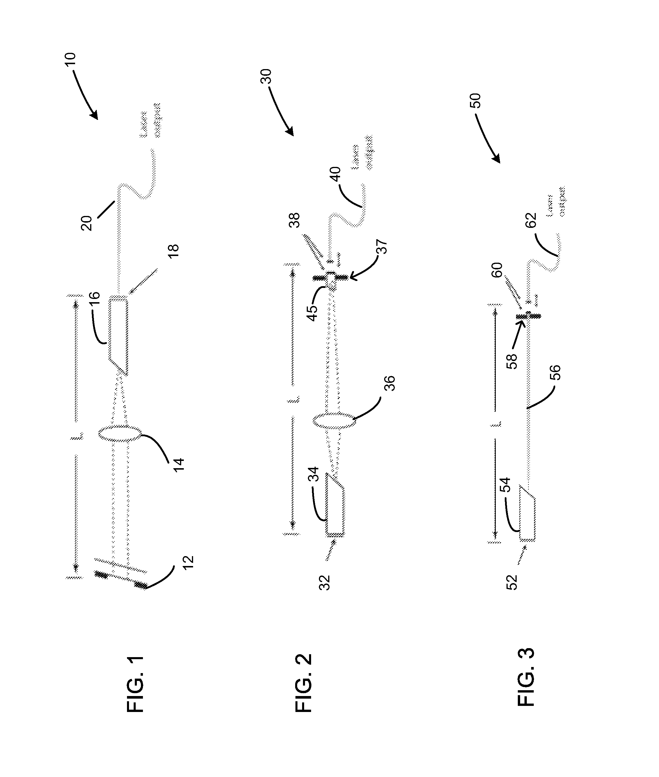
[0049]With respect to FIG. 1, the laser embodiment 10 shown includes a SOA 16, with one partially reflecting facet 18, and a etalon 12. In one embodiment, the etalon 12 is a tunable reflection-mode Fabry-Perot etalon. A lens 14 is also disposed in the cavity. The length of the laser cavity L is set by the distance between the partially reflecting surface 18 of the SOA and one surface of the etalon 12. A tapered fiber 20 couples the light out of the partially reflecting facet 18 of the SOA. In one embodiment, this laser 10 only includes a single lens 14. As a result, the cavity length L can be reduced relative to a cavity with additional lenses or other elements disposed therein. In addition, this design makes alignment easier, and reduces the internal reflections from the surfaces of the lens. In one embodiment, L ranges from about 0.5 to about 2 cm.

embodiment 30

[0050]Another embodiment of a short-cavity laser 30, shown in FIG. 2, includes a SOA 34, with one reflecting facet 32, and an etalon 37. In one embodiment, the etalon 37 operates in the transmission mode. The etalon can be a tunable fiber-optic Fabry-Perot etalon. A lens 36 is disposed in the cavity. An optical fiber 40 is also optically in communication with SOA 34. The length of the laser cavity L is set by the distance between the partially reflecting surface 32 of the SOA and the reflective coating 38 on the tip of the optical fiber 40 that forms one surface of the etalon. One advantage of this laser embodiment 30 is that it includes a tunable etalon 37, which is based on a piezo-actuated optical fiber 45 instead of a pair of electrostatically actuated plates. With respect FIG. 2, in one embodiment, L also ranges from about 0.5 to about 2 cm.

[0051]Similar to the embodiment of FIG. 1, only one lens 36 is used. This follows because the optical fiber 40 also couples light out of th...


PUM


Abstract

In part, the invention relates to frequency-domain optical coherence tomography system. The system includes a tunable laser comprising a laser output for transmitting laser light and a laser cavity having a length L, a gain element disposed within the laser cavity; a tunable wavelength selective element disposed within the laser cavity; a reference reflector disposed outside of the laser cavity; an interferometer in optical communication with the laser output and the reference reflector, wherein the interferometer is configured to transmit a portion of the laser light to a sample and combine light scattered from the sample with light scattered from the reference reflector; and a detector in optical communication with the interferometer that receives the combination of light scattered from the sample and the light scattered from the reference reflector and transforms the combination of light into an electronic signal comprising measurement data with respect to the sample.

Description

FIELD OF INVENTION[0001]In part, this invention relates to light sources and associated devices and methods for interferometric data collection systems, such as optical coherence tomography systems.BACKGROUND[0002]Frequency-domain optical coherence tomography (FD-OCT) systems employ light generated by a source such as a laser to collect data with respect to a sample. This data can be used to form cross-sectional images of biological tissue and other samples. Typically, lasers with fixed cavity lengths longer than 50 cm are used in FD-OCT systems. These fixed long-cavity length laser are relatively easy to construct using conventional fiber or free-space optical components.[0003]When tuned over a wide band of wavelengths, lasers with fixed cavity lengths traverse longitudinal modes spaced by an optical frequency interval equal to Δυ=c / 2 L, where L is the length of the laser cavity. Therefore, the longer the laser cavity, the more modes are available to sustain laser oscillation withi...

Claims


Application Information

Patent Timeline
Patent Type & Authority Patents(United States)
IPC IPC(8): H01S3/10G01B9/02
CPCG01B9/02004G01B9/02091G01B9/02069H01S3/1062H01S5/141
Inventor SCHMITT, JOSEPH M.
Owner LIGHTLAB IMAGING
Why Eureka
Try Eureka