
Wireless passive radiation sensor

a passive radiation sensor and wireless technology, applied in the field of radiation detection, can solve the problems of reducing the energy available for sensing measurement, increasing the fabrication cost during dicing and packaging, and being limited by the expense and portability of the readout hardwar

Active Publication Date: 2013-12-03
NAT TECH & ENG SOLUTIONS OF SANDIA LLC
View PDF5 Cites 21 Cited by
  • Summary
  • Abstract
  • Description
  • Claims
  • Application Information

AI Technical Summary

Benefits of technology

The patent is about a small and easy-to-use radiation sensor that can detect the presence or absence of radiation using a special film that changes from high resistance to low resistance when exposed to radiation. The sensor does not require batteries and can be read using a single antenna and data acquisition system. The patent also describes an addressable array of these sensors that can be used for radiation detection in an environment. The self-identifying sensors in the array have different resonance frequencies and delays, allowing for the manufacture of large and cost-effective sensor element arrays.

Problems solved by technology

This bit sequence requires each part on the wafer to have a unique photo-mask and thus increases fabrication cost during dicing and packaging due to tracking requirements on that unique part.
In addition, some of the energy received by the SAW device via the antenna is used for the identification and thus reduces the energy available for the sensing measurement.
This type of sensor response is good for monitoring pressure, strain, and torque, but is limited by the expense and portability of the readout hardware.
Further, SAW devices typically operate at frequencies in the range of 100 MHz to several GHz, making the monitoring of the phase and individual waves impractical for portable, inexpensive systems.
Existing small radiation detectors do not produce an immediate real-time warning of radiation doses because the detectors need to be sent to a lab for readout, which can require days or weeks to complete.
Other detectors are fragile, need human interpretation of colors, cost hundreds of dollars each or are not easily mass produced.

Method used


Image

  • Wireless passive radiation sensor
  • Wireless passive radiation sensor
  • Wireless passive radiation sensor

Examples


Embodiment Construction

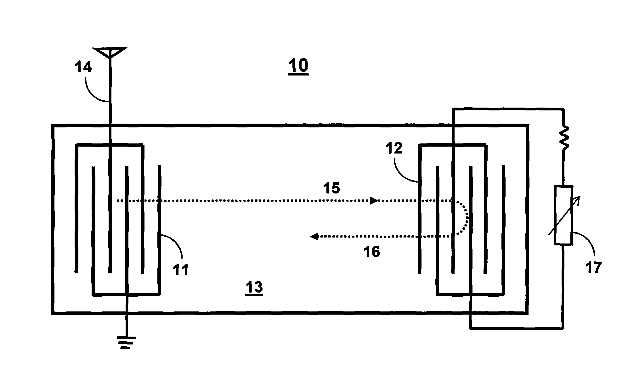
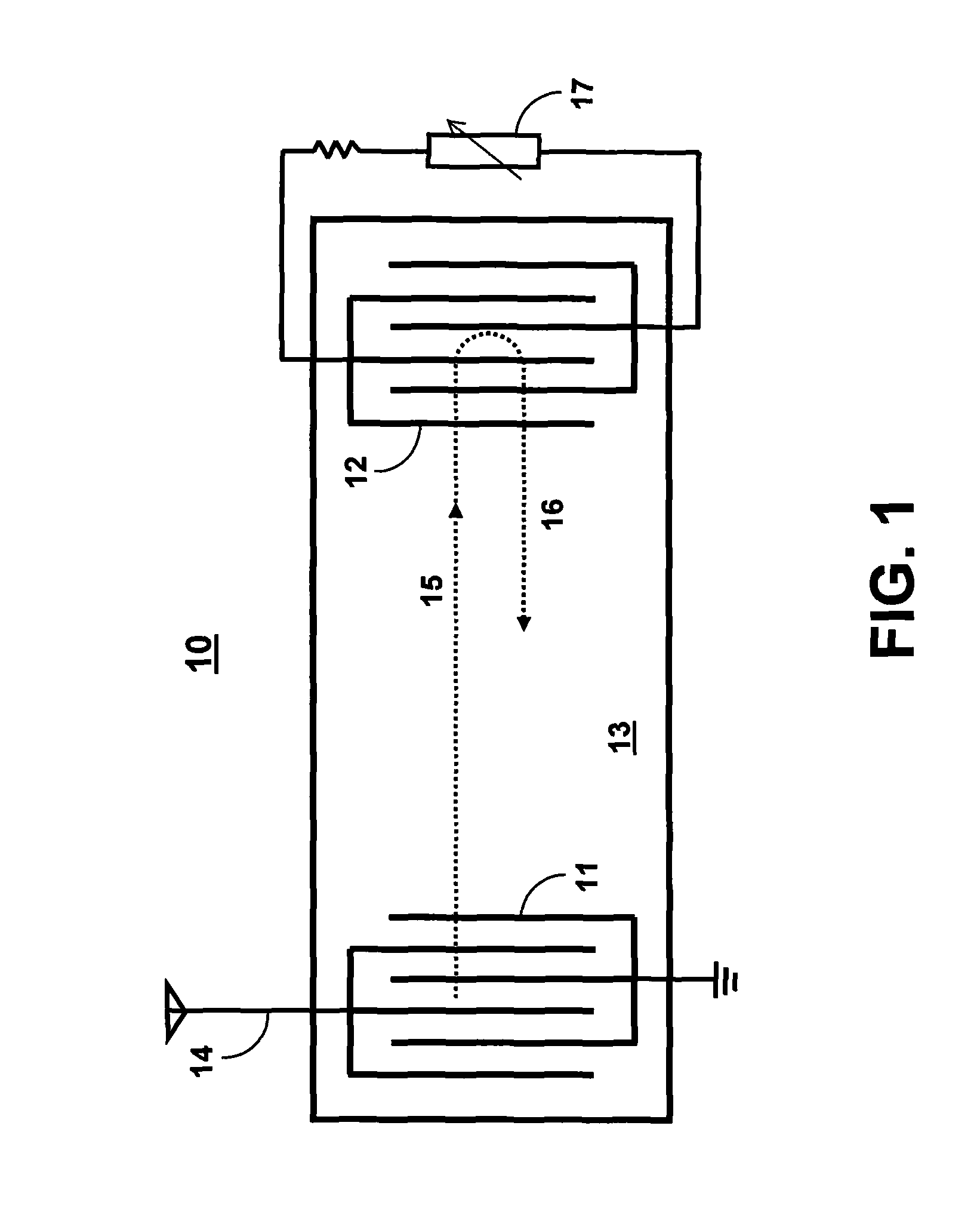
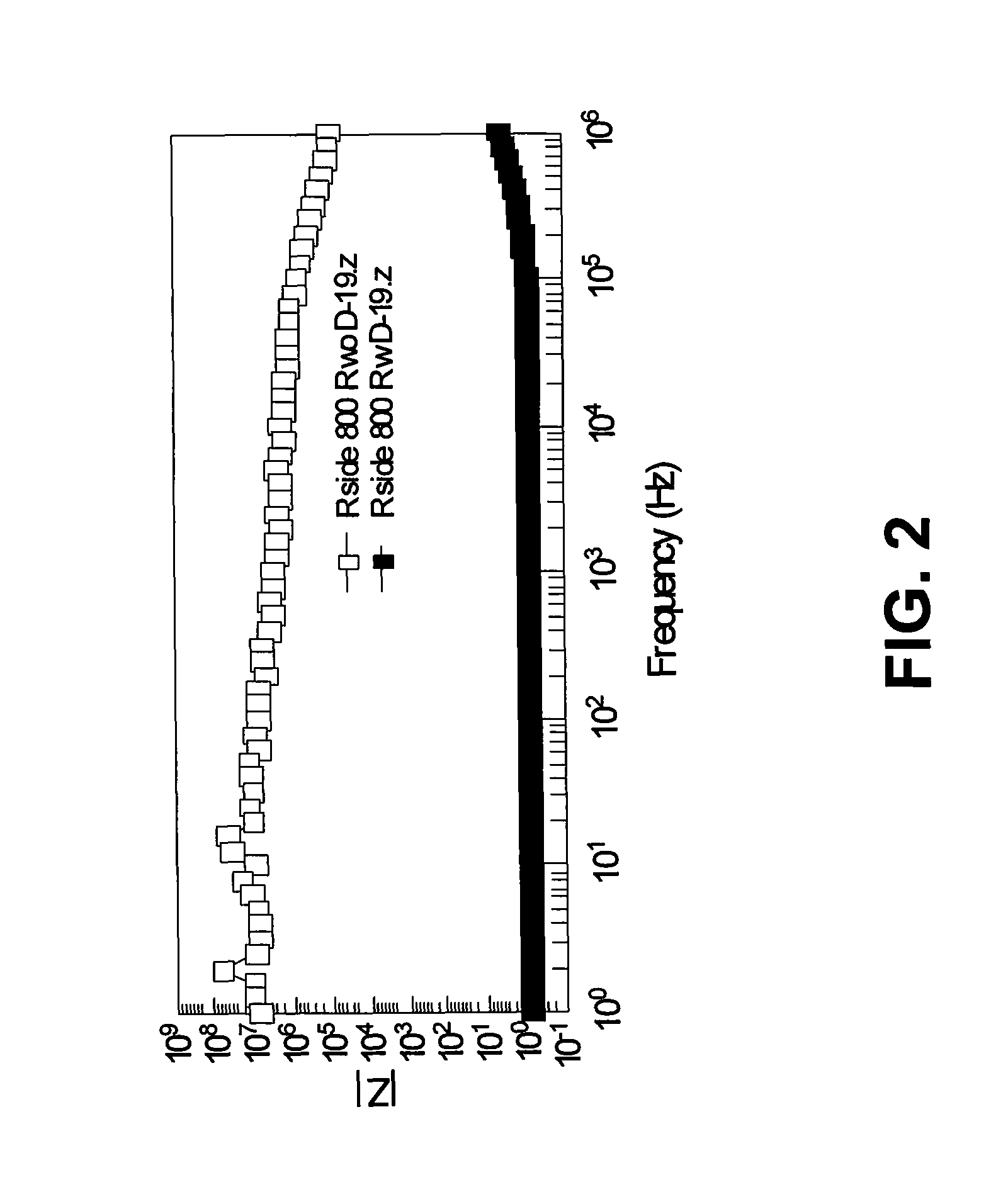
[0017]The wireless passive radiation sensor of the present invention is based on the change in minimum insertion loss of a SAW delay line due to a radiation-induced change in the impedance of a radiation-sensitive film. FIG. 1 is a schematic illustration of a wireless passive radiation sensor 10 of the present invention. The sensor 10 uses a SAW delay line, comprising two opposing comb-like interdigital transducers (IDTs): a launch IDT 11 and a sensor IDT 12. Each IDT comprises a fingerlike periodic pattern of parallel in-plane electrodes that can be photo-lithographically patterned on the surface of a piezoelectric substrate 13. The substrate 13 preferably comprises a piezoelectric material with a high mechanical coupling coefficient, such as LiNbO3, LiTaO3, GaAs, quartz, or other suitable piezoelectric substrate. Delay is determined by the center-to-center spacing between the opposing transducers 11 and 12. The resonant frequency is determined by the speed of sound in the piezoele...


PUM


Abstract

A novel measurement technique is employed using surface acoustic wave (SAW) devices, passive RF, and radiation-sensitive films to provide a wireless passive radiation sensor that requires no batteries, outside wiring, or regular maintenance. The sensor is small (<1 cm2), physically robust, and will operate unattended for decades. In addition, the sensor can be insensitive to measurement position and read distance due to a novel self-referencing technique eliminating the need to measure absolute responses that are dependent on RF transmitter location and power.

Description

CROSS-REFERENCE TO RELATED APPLICATION[0001]This application is a continuation-in-part of application Ser. No. 12 / 871,602, filed Aug. 30, 2010, now U.S. Pat. No. 8,240,911 which is incorporated herein by reference.STATEMENT OF GOVERNMENT INTEREST[0002]This invention was made with Government support under contract no. DE-AC04-94AL85000 awarded by the U.S. Department of Energy to Sandia Corporation. The Government has certain rights in the invention.FIELD OF THE INVENTION[0003]The present invention relates to radiation detection and, in particular, to a wireless passive radiation sensor.BACKGROUND OF THE INVENTION[0004]Surface acoustic wave (SAW) devices have been demonstrated to function linearly as sensors over a broad variation of physical quantities and they have been employed as wireless tags for tracking of high-value assets in addition to various types of wireless sensors. See M. Viens and J. D. N. Cheeke, “Highly Sensitive Temperature Sensor Using SAW Resonator Oscillator,”Sen...

Claims


Application Information

Patent Timeline
IPC IPC(8): G01K11/26
CPCG01K11/265G01K17/00
Inventor PFEIFER, KENT B.RUMPF, ARTHUR N.YELTON, WILLIAM G.LIMMER, STEVEN J.
Owner NAT TECH & ENG SOLUTIONS OF SANDIA LLC
Learn More