Semiconductor memory device and driving method thereof
a memory device and semiconductor technology, applied in the field of memory devices, can solve the problems of failure to respond, extremely unstable output potential in this region, loss of data, etc., and achieve the effects of reducing power consumption, reducing power consumption, and reducing power consumption
- Summary
- Abstract
- Description
- Claims
- Application Information
AI Technical Summary
Benefits of technology
Problems solved by technology
Method used
Image
Examples
embodiment 1
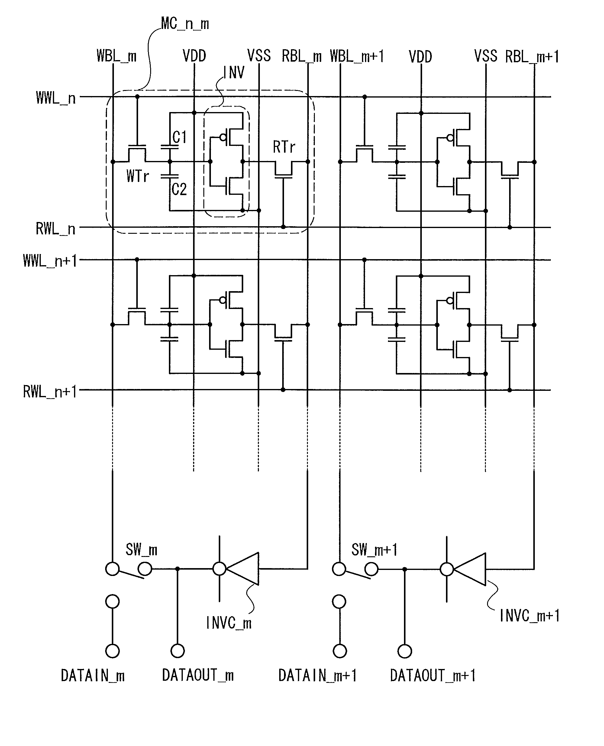
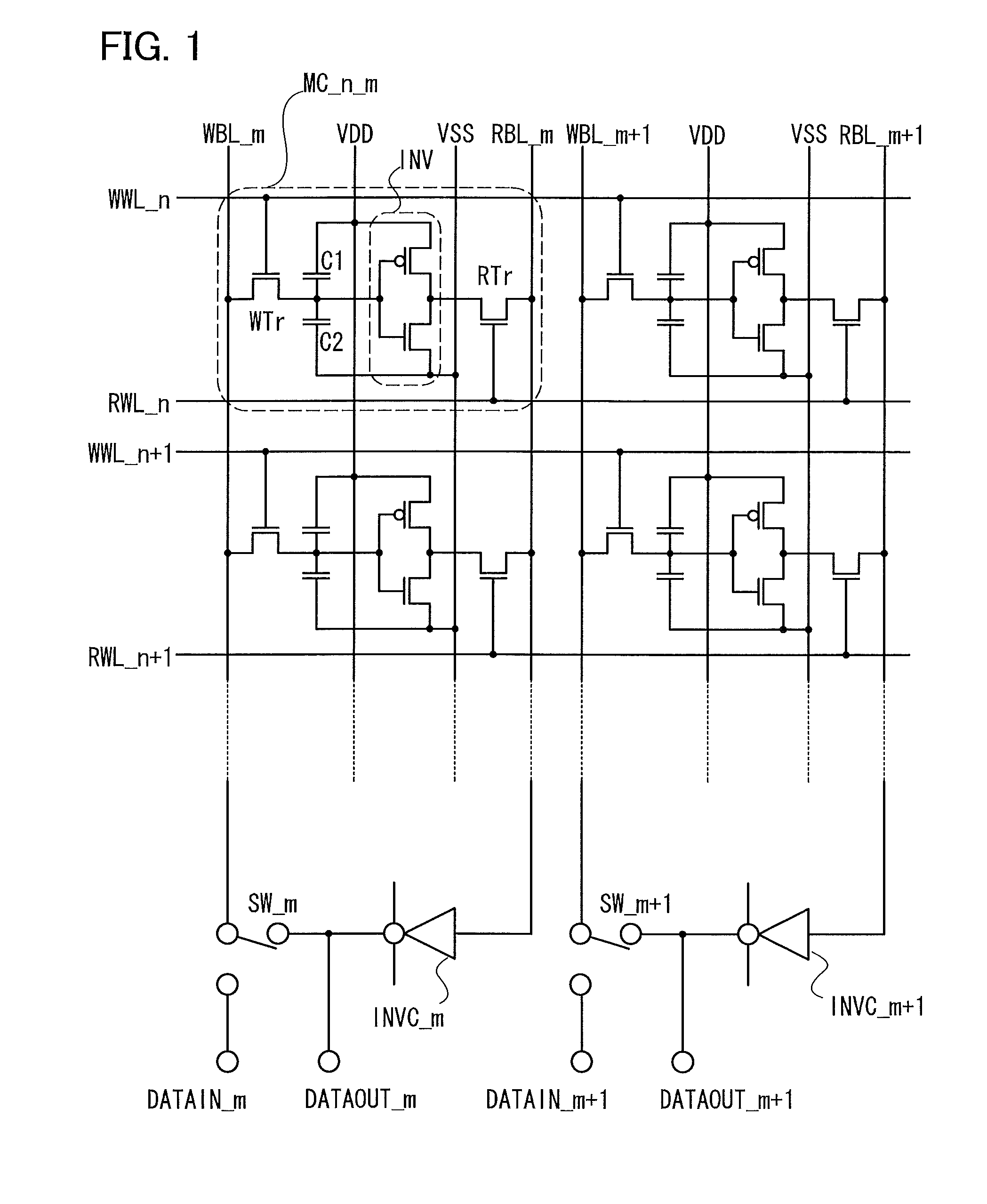
[0072]In this embodiment, the semiconductor memory device in FIG. 1 and an operational example thereof will be described with reference to FIGS. 3A to 3F. A semiconductor device in this embodiment includes write word lines WWL, read word lines RWL, write bit lines WBL orthogonal to the write word lines, read bit lines RBL orthogonal to the read word lines, and memory cells.
[0073]FIG. 1 illustrates a memory cell in the n-th row and m-th column, a memory cell in the (n+1)-th row and m-th column, a memory cell in the n-th row and the (m+1)-th column, and a memory cell in the (n+1)-th row and (m+1)-th column, and the write word lines WWL, read word lines RWL, write bit lines WBL, and read bit lines RBL which relate to these memory cells.
[0074]Each memory cell includes a write transistor WTr, a read transistor RTr, an inverter INV, and capacitors C1 and C2. The capacitor C1 or the capacitor C2, or both may be provided unintentionally.
[0075]The drain of the write transistor WTr is connect...
embodiment 2
[0117]This embodiment will be described with reference to FIG. 1 and FIGS. 4A to 4C. In the writing method in Embodiment 1, during the write operation, the write transistor WTr is turned on by operating the write word line WWL, so that all the write transistors WTr connected to one write word line WWL are turned on. Consequently, charges stored on the capacitors connected to the sources of all the write transistors WTr in that row is lost.
[0118]This embodiment will give the description of a method in which data are rewritten to only, of the memory cells connected to the write word line WWL, ones in the columns that need to be rewritten, and the same data as those stored before are automatically written to the others.
[0119]FIGS. 4A to 4C show an example. Here, the potential of the positive electrode of the inverter INV is +0.8 V, and the potential of the negative electrode of the inverter INV is 0 V. As illustrated in FIG. 4A, for the memory cell in the n-th row and the m-th column (...
embodiment 3
[0130]In this embodiment, modified examples of the semiconductor memory device in FIG. 1 will be described with reference to FIGS. 5A to 5C. In the memory cell illustrated in FIG. 5A, the write bit line for the adjacent memory cell is used as a substitute of the read bit line. In other words, the bit line BL_m+1 is the read bit line for the memory cell in the n-th row and the m-th column (MC_n_m) and also the write bit line for the memory cell in the n-th row and the (m+1)-th column.
[0131]In the memory cell in FIG. 5B, the write bit line used for this memory cell is a substitute of the read bit line. In other words, the bit line BL_m the read bit line for the memory cell in the n-th row and the m-th column and also the write bit line used for this memory cell.
[0132]The memory cell in FIG. 5C is one in which the inverter is not a complementary inverter but a resistive load inverter. In other words, a resistor R is used instead of the p-type transistor in the inverter INV_n_m included...
PUM
 Abstract
Description
Claims
Application Information
 - R&D
- Intellectual Property
- Life Sciences
- Materials
- Tech Scout
- Unparalleled Data Quality
- Higher Quality Content
- 60% Fewer Hallucinations
Browse by: Latest US Patents, China's latest patents, Technical Efficacy Thesaurus, Application Domain, Technology Topic, Popular Technical Reports.
© 2025 PatSnap. All rights reserved.Legal|Privacy policy|Modern Slavery Act Transparency Statement|Sitemap|About US| Contact US: help@patsnap.com


