Method for manufacturing a laser welded steel pipe

a technology of laser welding and steel pipes, which is applied in the field of methods for manufacturing steel pipes, can solve the problems of deterioration of the corrosion resistance of the seam, the problem of line and the inability to manufacture steel pipes based on electric resistance welded steel pipes. achieve the effect of stable and high yield ra

Inactive Publication Date: 2013-12-10
JFE STEEL CORP
View PDF13 Cites 14 Cited by
  • Summary
  • Abstract
  • Description
  • Claims
  • Application Information

AI Technical Summary

Benefits of technology

[0035]With the present invention, the status of laser welding can be accurately assessed during the manufacturing of laser welded steel pipes, and the assessment can be used to modify welding conditions so that the contact point of the longitudinal edges can be always located in keyhole(s) or molten metal formed by irradiation with laser beam(s). As a result, laser welded steel pipes can be manufactured at a high yield rate and in a stable manner. The obtained laser welded steel pipes are excellent in terms of the low-temperature toughness and the corrosion resistance of the seam thereof and thus can be suitable for the use as oil country tubular goods or line pipes that are used in cold districts or the corrosion environment.

Problems solved by technology

Thus, oil country tubular goods and line pipes based on electric resistance welded steel pipes have a problem with the use in cold districts.
Electric resistance welded steel pipes have another problem: Alloy elements often segregate in molten metal while the longitudinal edges are being welded, and thus the corrosion resistance of the seam is often deteriorated.
Thus, oil country tubular goods and line pipes based on electric resistance welded steel pipes have a problem with the use in the harsh corrosion environment (e.g., the sour environment).
However, the plasma illumination scatters over a wide area, and thus, with this technique, it is difficult to have an accurate understanding of the status of laser welding and impossible to detect any shift of the position of irradiation with the laser beam from the longitudinal edges accurately.
However, the emission intensity greatly varies because of various factors, and thus, with this technique, it is difficult to have an accurate understanding of the formation status of penetration beads.
The direct application of this technique for arc welding to laser welding fails to provide a clear image of molten metal.
This is because in laser welding, heat energy converges to a high density, and thus an excessive light intensity is generated.
As a result, it is difficult in laser welding to have an accurate understanding of the shape of penetration beads.
In addition, Japanese Unexamined Patent Application Publication No. 2001-25867 discloses a technique of irradiating molten metal with a laser beam through an interference filter; however, this laser beam is used to image molten metal and thus has no contribution to welding.

Method used


Image

  • Method for manufacturing a laser welded steel pipe
  • Method for manufacturing a laser welded steel pipe
  • Method for manufacturing a laser welded steel pipe

Examples


example 1

[0078]Laser welded steel pipes were manufactured by forming steel strips into cylindrical open pipes with forming rolls and then irradiating each open pipe with a laser beam from the side of the outer surface while compressing the longitudinal edges of the open pipe using squeeze rolls. Components of the steel strips were as shown in Table 1.

[0079]In laser welding, a 25-kW CO2 laser oscillator was used, the power and welding speed of which were as shown in Table 2.

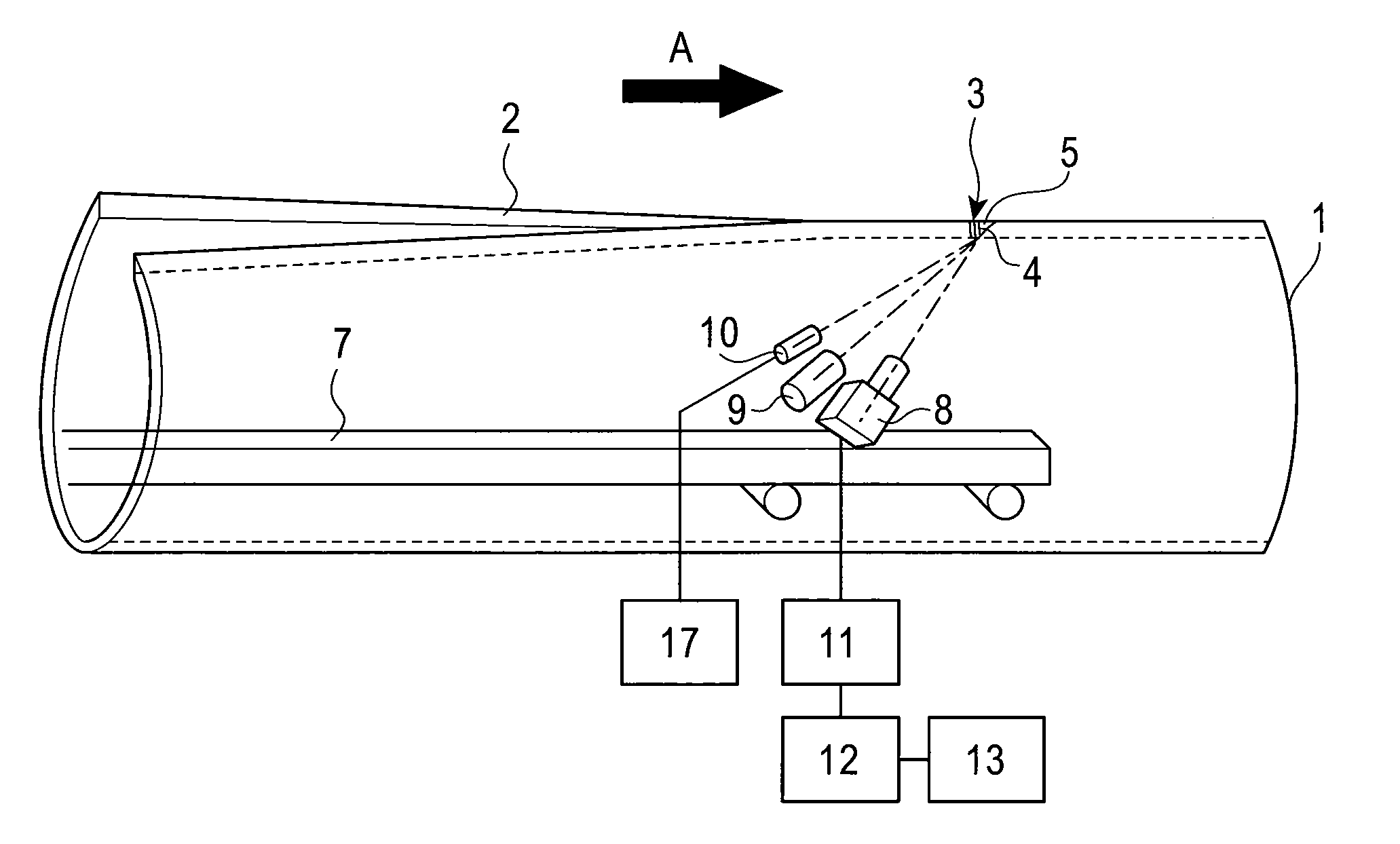
[0080]A monitoring device for the keyhole 4 was a monitoring camera 8 attached using the device shown in FIG. 3 to the mandrel bar 7 of a device for cutting inner beads, and was inserted into each open pipe 1. Note that the plasma illumination sensor 10 and the monitoring device 17 for it were not used, although shown in FIG. 3. The monitoring camera 8 was a camera that could visualize the predefined wavelength (i.e., 337 nm) only, in order to prevent disturbance due to light such as plasma illuminations generated by irrad...

example 2

[0088]Laser welded steel pipes were manufactured by forming steel strips into cylindrical open pipes with forming rolls and then irradiating each open pipe with a laser beam 3 from the side of the outer surface while compressing the longitudinal edges 2 of the open pipe 1 using squeeze rolls. Additionally, a plasma jet or a TIG arc was used as an auxiliary heat source, and the auxiliary heat was so placed that they could heat the longitudinal edges 2 before the laser beam 3 did. Components of the steel strips were as shown in Table 3.

[0089]In laser welding, a 20-kW fiber laser oscillator was used, the power and welding speed of which were as shown in Table 4.

[0090]A monitoring device for the keyhole 4 was a monitoring camera 8 attached using the device shown in FIG. 3 to the mandrel bar 7 of a device for cutting inner beads, and was inserted into each open pipe 1. Note that the plasma illumination sensor 10 and the monitoring device 17 for it were not used, although shown in FIG. 3....

example 3

[0096]Laser welded steel pipes were manufactured by forming steel strips into cylindrical open pipes with forming rolls and then irradiating each open pipe with a laser beam from the side of the outer surface while compressing the longitudinal edges of the open pipe using squeeze rolls. Additionally, a TIG arc was used as auxiliary heating means, and the arc was so placed that it could heat and melt the longitudinal edges before the laser beam did. Components of the steel strips were as shown in Table 5.

[0097]In laser welding, a 10-kW fiber laser oscillator was used, the power and welding speed of which were as shown in Table 6.

[0098]A monitoring device for the keyhole was a monitoring camera 8 attached using the device shown in FIG. 3 to the mandrel bar 7 of a device for cutting inner beads, and was inserted into each open pipe 1. Note that the plasma illumination sensor 10 and the monitoring device 17 for it were not used, although shown in FIG. 3. The monitoring camera 8 was a ca...


PUM

PropertyMeasurementUnit
diameteraaaaaaaaaa
lengthaaaaaaaaaa
distanceaaaaaaaaaa

Abstract

There is provided a method for manufacturing a laser welded steel pipe in which the status of laser welding is accurately assessed, and the assessment is used to modify welding conditions, so that laser welded steel pipes can be manufactured at a high yield rate and in a stable manner. Irradiation point(s) of laser beam(s), with which the longitudinal edges are irradiated from the side of the outer surface, are monitored from the side of the inner surface of an open pipe, and then conditions of welding with the laser beam(s) are assessed to be kept unchanged if any keyhole is found penetrating out of the inner surface of the open pipe, or modified if no keyhole is found penetrating out of the inner surface of the open pipe.

Description

FIELD OF THE INVENTION[0001]The present invention relates to methods for manufacturing a steel pipe obtained by welding the longitudinal edges of an open pipe with a laser beam (hereinafter, referred to as a laser welded steel pipe), in particular, a method for manufacturing a laser welded steel pipe suitable for digging and transportation of oil and natural gas, such as oil country tubular goods or a line pipe.BACKGROUND OF THE INVENTION[0002]Steel pipes known as oil country tubular goods or line pipes fall into two broad categories: welded steel pipes (e.g., electric resistance welded steel pipes and UOE steel pipes) and seamless steel pipes. Of these kinds of steel pipes, electric resistance welded steel pipes can be manufactured at low cost by using a hot rolled steel strip (so-called a hot rolled steel coil) as the raw material and thus are economically advantageous.[0003]However, electric resistance welded steel pipes are usually manufactured by forming steel strips into cylin...

Claims


Application Information

Patent Timeline
Patent Type & Authority Patents(United States)
IPC IPC(8): B23K26/00
CPCB23K26/03B23K26/032B23K26/1429B23K26/265B23K2201/06B23K2201/10B23K2203/04B23K26/262B23K26/348B23K2101/06B23K2101/10B23K2103/04B21C37/08
Inventor YANO, KOJIOI, KENJISUZUKI, MASAHITOKODAMA, TOSHIFUMISAKASHITA, SHIGETO
Owner JFE STEEL CORP
Why Eureka
Try Eureka