Rotational atherectomy segmented abrading head and method to improve abrading efficiency

a technology of atherectomy and abrading head, which is applied in the field of rotational atherectomy segmented abrading head and improving abrading efficiency, can solve the problems of stent restenosis, blockage of blood flow, and angina

Active Publication Date: 2014-01-14
CARDIOVASCULAR SYST INC
View PDF20 Cites 50 Cited by
  • Summary
  • Abstract
  • Description
  • Claims
  • Application Information

AI Technical Summary

Benefits of technology

[0012]The invention provides a rotational atherectomy system, device and method having, in various embodiments, a flexible, elongated, rotatable drive shaft comprising an eccentric abrading head comprising at least one eccentric abrading cylindrical segment attached to the drive shaft and in spaced proximity with proximal and distal abrading segments. Each individual abrading segment, comprises a first tissue removing surface, typically an abrasive coating on the outer surface, that is designed to abrade calcified, hard tissue and abrasive coating on the leading and trailing surfaces designed to abrade non-calcified, soft tissue. Each abrading segment, as well as the abrading head comprising the collective segments, has a center of mass spaced radially from the rotational axis of the drive shaft, facilitating the ability of the device to open the stenotic lesion to a diameter larger than the outer diameter of the enlarged abrading head when operated at high speeds.
[0017]Another object of the invention is to provide a high-speed rotational atherectomy device comprising an eccentric abrading head comprising at least one eccentric abrading cylindrical segment attached to the drive shaft and proximal and distal segments, the at least one eccentric abrading cylindrical segment in spaced proximity with both the proximal and distal segments and further comprising a customizable eccentricity for the abrading head during high-speed rotation by adding or subtracting additional eccentric abrading cylindrical segments from the abrading head, thus customizing the amount of mass comprising the abrading head and manipulating the center off mass offset from the rotational axis of the drive shaft.
[0018]Another object of the invention is to provide a high-speed rotational atherectomy device comprising an eccentric abrading head comprising at least one eccentric abrading cylindrical segment attached to the drive shaft and proximal and distal segments, the at least one eccentric abrading cylindrical segment in spaced proximity with both the proximal and distal conical segments and further comprising a center of mass that is offset from the rotational axis of the atherectomy device's drive shaft, wherein the proximal spacing of the at least one eccentric abrading cylindrical segment provides for flexibility of the abrading head during movement through tortuous vasculature.
[0019]Another object of the invention is to provide a high-speed rotational atherectomy device having at least one eccentric abrading cylindrical segment attached to the drive shaft and proximal and distal segments, the at least one eccentric abrading cylindrical segment in spaced proximity with both the proximal and distal segments and comprising complete gaps therebetween, the gaps improving efficacy in abrading non-calcified and / or soft stenotic tissue.
[0020]Another object of the invention is to provide a high-speed rotational atherectomy device having at least one eccentric abrading head comprising at least one eccentric abrading cylindrical segment attached to the drive shaft and proximal and distal segments, the at least one eccentric abrading cylindrical segment in spaced proximity with both the proximal and distal conical segments, the gap between adjacent cylindrical segments and / or cylindrical segment and the proximal and distal segments facilitating breaking the hydraulic wedge between the tissue removing surface and the stenotic tissue.

Problems solved by technology

If left untreated, such stenoses can cause angina, hypertension, myocardial infarction, strokes and the like.
Studies have shown, however, that a significant percentage of patients who have undergone balloon angioplasty and had a stent placed in an artery experience stent restenosis—i.e., blockage of the stent which most frequently develops over a period of time as a result of excessive growth of scar tissue within the stent.
As the burr is removing stenotic tissue, however, it blocks blood flow.
This flexion allows for a larger diameter opening during high speed operation, but may also provide less control than desired over the diameter of the artery actually abraded.
In addition, some stenotic tissue may block the passageway so completely that the Shturman device cannot be placed therethrough.
Since Shturman requires that the enlarged eccentric section of the drive shaft be placed within the stenotic tissue to achieve abrasion, it will be less effective in cases where the enlarged eccentric section is prevented from moving into the stenosis.
This construction is limited, however because, as Clement explains at Col. 3, lines 53-55, that the asymmetrical burr is rotated at “lower speeds than are used with high speed ablation devices, to compensate for heat or imbalance.” That is, given both the size and mass of the solid burr, it is infeasible to rotate the burr at the high speeds used during atherectomy procedures, i.e., 20,000-200,000 rpm.
Essentially, the center of mass offset from the rotational axis of the drive shaft would result in development of significant centrifugal force, exerting too much pressure on the wall of the artery and creating too much heat and excessively large particles.
In general, current tissue-removing elements are of a one-piece solid design which is inflexible and, as a result, may be difficult to advance / retract through tortuous vasculature.
It is known that a hydraulic wedge forms in some cases between the current tissue-removing element design and the arterial wall and plaque, reducing the contact between the abrasive and the plaque and, as a result, reducing the efficacy of the procedure.
Moreover, the relatively smooth abrasive face of current designs does not maximize abrading and / or cutting efficacy.
Finally, the known relatively smooth tissue-removing element designs result in atherectomy procedures of unpredictable length when working with soft plaque and / or non-calcified lesions and / or diffuse lesions.

Method used


Image

  • Rotational atherectomy segmented abrading head and method to improve abrading efficiency
  • Rotational atherectomy segmented abrading head and method to improve abrading efficiency
  • Rotational atherectomy segmented abrading head and method to improve abrading efficiency

Examples


Embodiment Construction

[0034]While the invention is amenable to various modifications and alternative forms, specifics thereof are shown by way of example in the drawings and described in detail herein. It should be understood, however, that the intention is not to limit the invention to the particular embodiments described. On the contrary, the intention is to cover all modifications, equivalents, and alternatives falling within the spirit and scope of the invention.

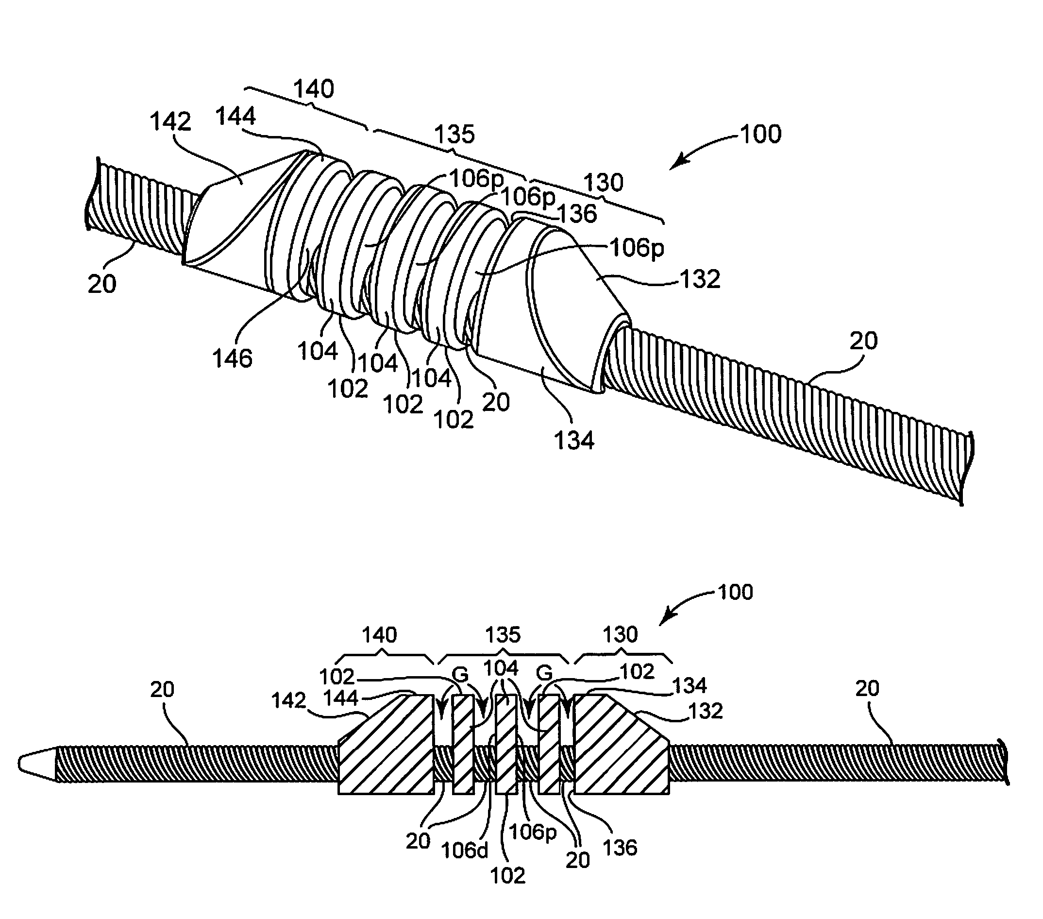
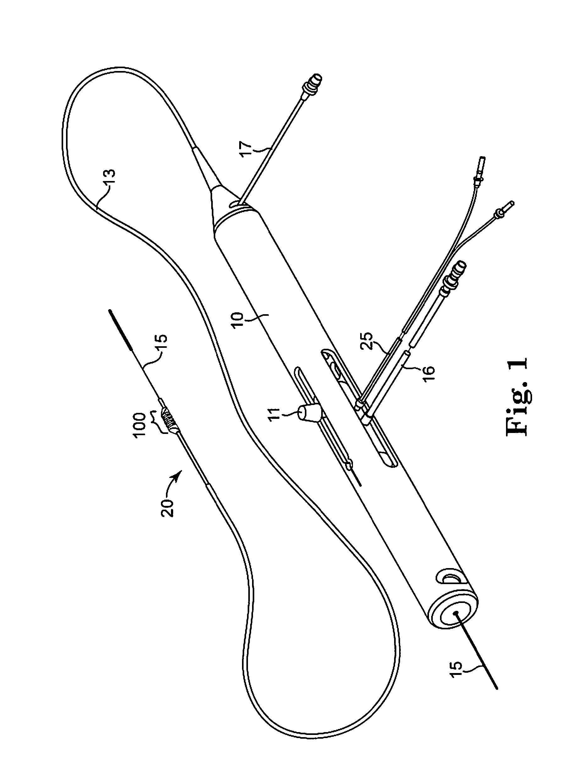
[0035]FIG. 1 illustrates one embodiment of a rotational atherectomy device according to the present invention. The device includes a handle portion 10, an elongated, flexible drive shaft 20 having an eccentric abrading head 100. As will be discussed herein, the abrading head 100 comprising a proximal and distal segment with an intermediate section comprising at least one eccentric cylindrical segment therebetween. An elongated catheter 13 extending distally from the handle portion 10. The drive shaft 20 is constructed from helically coiled wi...


PUM


Abstract

The invention provides a rotational atherectomy system, device and method having, in various embodiments, a flexible, elongated, rotatable drive shaft comprising an eccentric abrading head comprising at least one eccentric abrading cylindrical segments attached to the drive shaft and in spaced proximity with proximal and a distal conical segments. Each individual abrading segment, comprises a first tissue removing surface, typically an abrasive coating on the outer surface, that is designed to abrade calcified, hard tissue and abrasive coating on the leading and trailing surfaces designed to abrade non-calcified, soft tissue. Each abrading segment, as well as the abrading head comprising the collective segments, has a center of mass spaced radially from the rotational axis of the drive shaft, facilitating the ability of the device to open the stenotic lesion to a diameter larger than the outer diameter of the enlarged abrading head when operated at high speeds.

Description

BACKGROUND OF THE INVENTION[0001]1. Field of the Invention[0002]The invention relates to systems, devices and methods for removing tissue from body passageways, such as removal of atherosclerotic plaque from arteries, utilizing a high-speed rotational atherectomy device.[0003]2. Description of the Related Art[0004]A variety of techniques and instruments have been developed for use in the removal or repair of tissue in arteries and similar body passageways. A frequent objective of such techniques and instruments is the removal of atherosclerotic plaques in a patient's arteries. Atherosclerosis is characterized by the buildup of fatty deposits (atheromas) in the intimal layer (under the endothelium) of a patient's blood vessels. Very often over time, what initially is deposited as relatively soft, cholesterol-rich atheromatous material hardens into a calcified atherosclerotic plaque. Such atheromas restrict the flow of blood, and therefore often are referred to as stenotic lesions or ...

Claims


Application Information

Patent Timeline
Patent Type & Authority Patents(United States)
IPC IPC(8): A61B17/22
CPCA61B2017/320004A61B17/320758A61B2017/320766
Inventor NARVESON, CHRISTOPHER, M.
Owner CARDIOVASCULAR SYST INC
Why Eureka
Try Eureka