Laser direct ablation with picosecond laser pulses at high pulse repetition frequencies

a laser pulse and high pulse repetition frequency technology, applied in the field of laser micromachining, can solve the problems of affecting throughput, lack of productive and cost effective manufacturing techniques suitable for high-volume production, and known methods of dielectric removal, etc., to achieve the effect of effective lda, sufficient pulse overlap, and more efficient and cleaner material removal

Active Publication Date: 2014-02-11
ELECTRO SCI IND INC
View PDF8 Cites 32 Cited by
  • Summary
  • Abstract
  • Description
  • Claims
  • Application Information

AI Technical Summary

Benefits of technology

[0004]Systems and methods use a short temporal pulsewidth laser with a high pulse repetition frequency for effective LDA processing. The high pulse repetition frequency allows the laser beam to move rapidly across the workpiece (for high throughput) while maintaining sufficient pulse overlap. The short temporal pulsewidth makes for more efficient and cleaner material removal. In certain embodiment, a UV laser is used. In other embodiments, a green laser is used.

Problems solved by technology

Known methods for dielectric removal, however, lack productive and cost effective manufacturing techniques suitable for high-volume production.
However, increasing pattern density may significantly impact throughput in the case of direct writing methods using a UV YAG laser.

Method used


Image

  • Laser direct ablation with picosecond laser pulses at high pulse repetition frequencies
  • Laser direct ablation with picosecond laser pulses at high pulse repetition frequencies
  • Laser direct ablation with picosecond laser pulses at high pulse repetition frequencies

Examples


Embodiment Construction

I. Overview

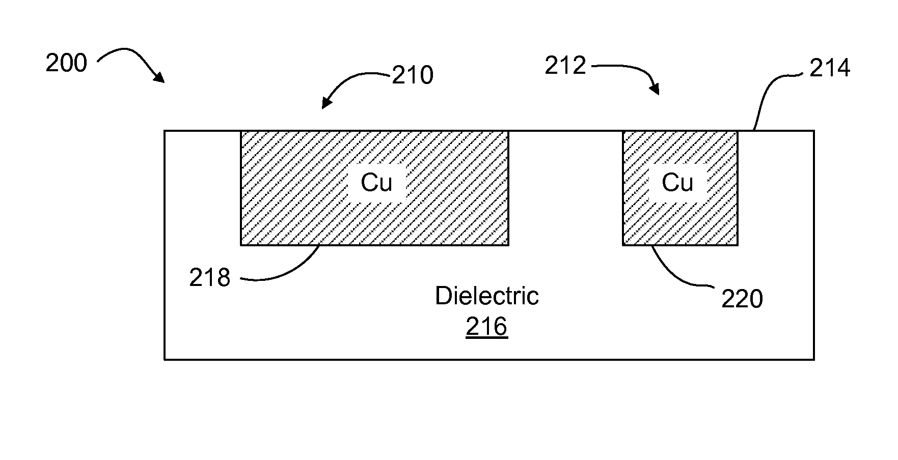
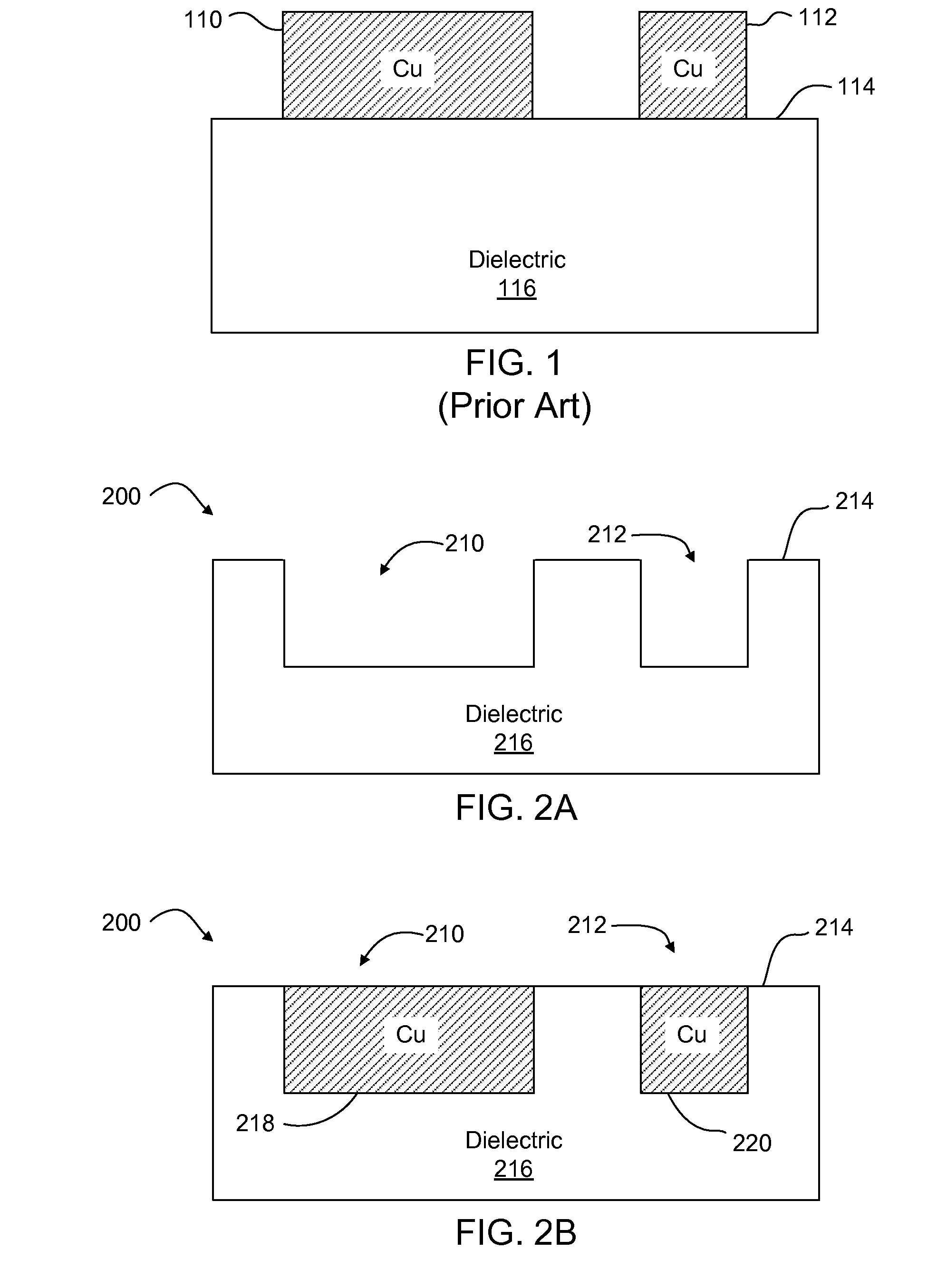
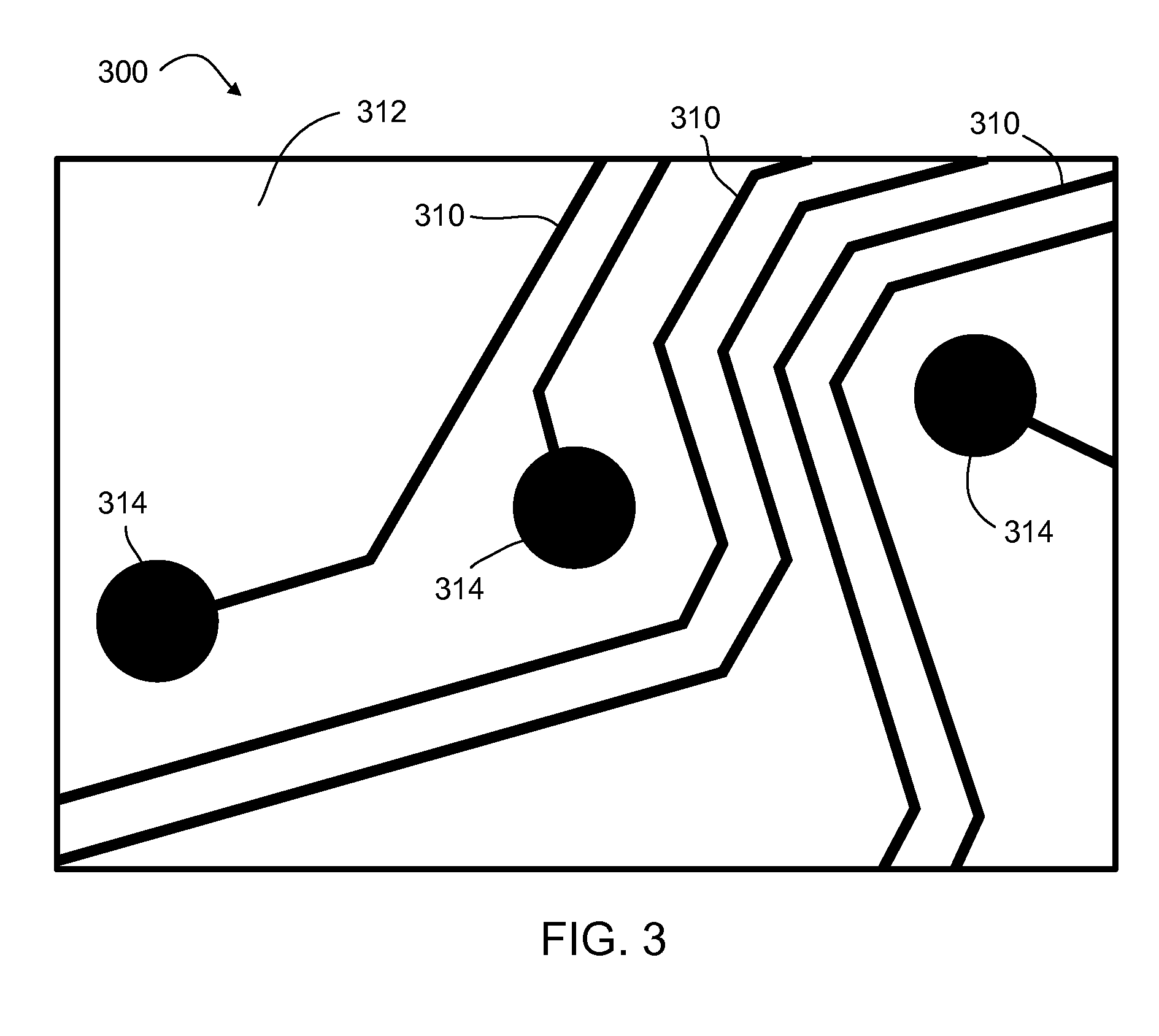
[0023]Systems and methods provide productive processing (e.g., using a vector scan approach) having a high throughput in a laser direct ablation (LDA) application. High-speed beam positioning and high pulse repetition frequencies (PRFs) provide sufficient overlap of successive laser pulses to control the uniformity and features of kerfs cut in a dielectric material. Known plating processes may then be used to form electrical paths in the kerfs with desired signal propagation characteristics (e.g., impedance, resistance, and capacitance).

[0024]In certain embodiments, a high-speed beam positioning scheme is used in combination with a mode locked laser. As beam positioning technology advances, the pulse repetition rate of the laser source becomes a limiting factor. For example, with a 10 μm spot size at a workpiece, a laser source running at 10 kHz pulse repetition frequency (PRF), and a velocity of the laser beam with respect to a surface of the workpiece higher than 100 mm...


PUM

PropertyMeasurementUnit
velocityaaaaaaaaaa
velocityaaaaaaaaaa
velocityaaaaaaaaaa

Abstract

Laser direct ablation (LDA) produces patterns cut into a dielectric layer for the formation of electrically conductive traces with controlled signal propagation characteristics. LDA processing includes selecting a dose fluence for removing a desired depth of material along a scribe line on a surface of a workpiece, selecting a temporal pulsewidth for each laser pulse in a series of laser pulses, and selecting a pulse repetition frequency for the series of laser pulse. The pulse repetition frequency is based at least in part on the selected temporal pulsewidth to maintain the selected dose fluence along the scribe line. The selected pulse repetition frequency provides a predetermined minimum overlap of laser spots along the scribe line. The LDA process further includes generating a laser beam including the series of laser pulses according to the selected dose fluence, temporal pulsewidth, and pulse repetition frequency.

Description

TECHNICAL FIELD[0001]This disclosure relates to laser micromachining. In particular, this disclosure relates to systems and methods for scribing patterns in a workpiece for the formation of electrically conductive traces with controlled signal propagation characteristics.BACKGROUND INFORMATION[0002]Integrated circuit (IC) substrate manufacturing technology aims to reduce substrate size and cost and to increase functionality. A recent advance uses laser direct ablation (LDA) and special plating processes to form electrical signal traces or paths inside a dielectric layer, as opposed to forming signal traces on the surface of the dielectric layer using conventional lithography technology. The embedded trace approach reduces overall layer counts, improves cost and yield, and improves electrical performance by reducing signal length and optimizing trace routing. The embedded trace approach may be achieved by forming signal traces having widths that are 10 μm or less in conjunction with ...

Claims


Application Information

Patent Timeline
Patent Type & Authority Patents(United States)
IPC IPC(8): B23K26/00B23K26/36
CPCB23K26/0807B23K26/4065B23K26/367B23K2201/42B23K26/0861B23K26/0652B23K26/0648B23K26/063B23K26/0622B23K26/082B23K26/364B23K2103/42B23K2103/50B23K2101/42H01L21/28H01L21/30
Inventor ALPAY, MEHMET E.MATSUMOTO, HISASHIUNRATH, MARK A.LI, GUANGYU
Owner ELECTRO SCI IND INC
Why Eureka
Try Eureka