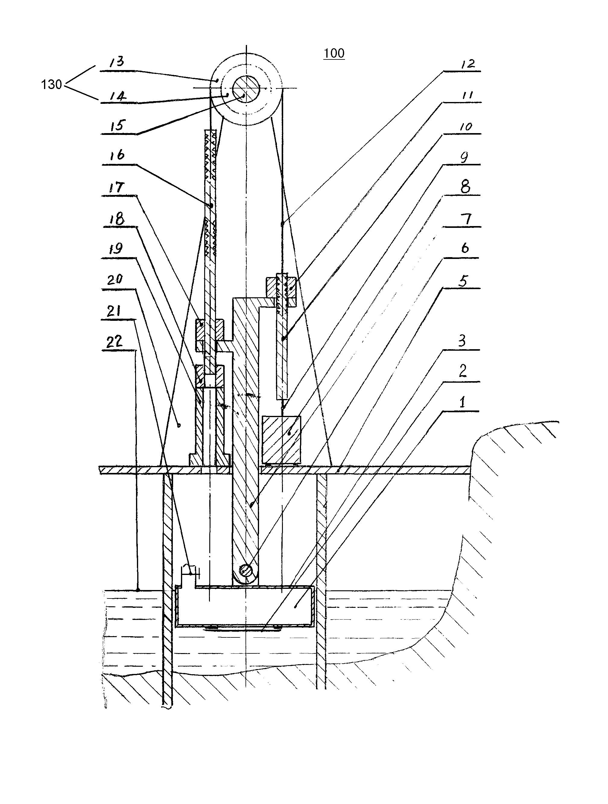
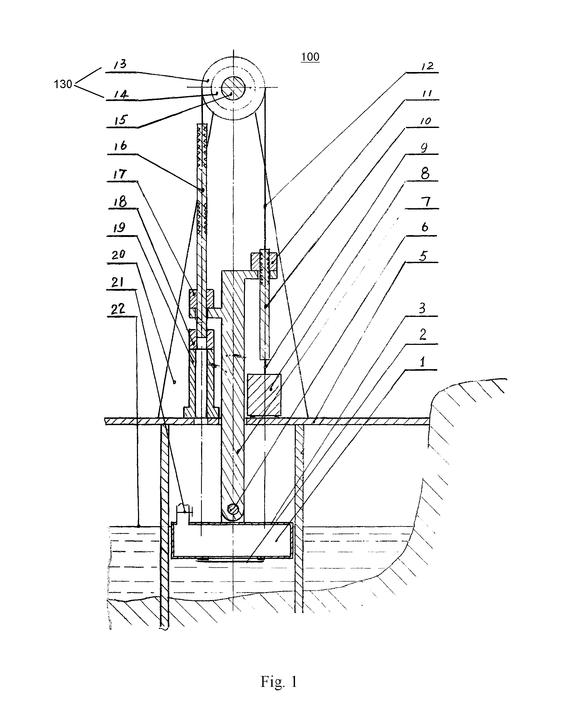
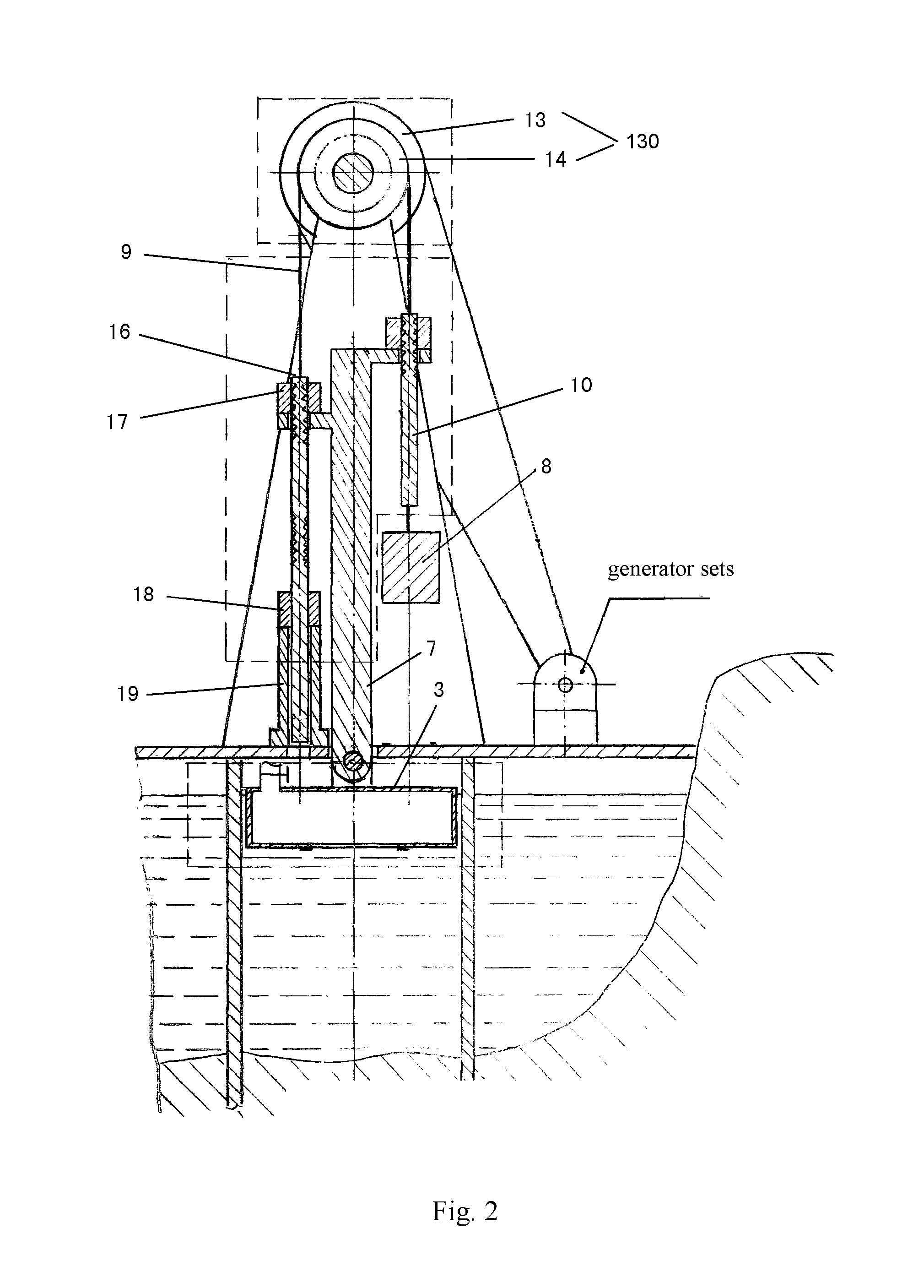
Method and system for tidal energy storage and power generation

a technology of tidal energy and power generation, applied in the field of methods, can solve the problems of inexhaustible or inability to use tide energy, affecting the development and utilization of tide energy, and double the work and cost of civil works and electromechanical equipment, so as to achieve the effect of significantly expanding the application scope of tide energy

Active Publication Date: 2014-02-11
SHANGHAI MEIPENG PURE CLEAN ENERGY TECH
View PDF7 Cites 4 Cited by
  • Summary
  • Abstract
  • Description
  • Claims
  • Application Information

AI Technical Summary

Benefits of technology

[0010]The purpose of the present invention is to overcome the disadvantages in the prior art, and improve the efficiency in the application of tidal energy.
[0011]The essential concept is to utilize rising and falling tides to lift energy storage components to a height which is approximately twice the tide height, thereby improving the efficiency in the application of tidal energy.

Problems solved by technology

And tides rise and fall each day, again and again, and the energy from tides is inexhaustible or can be used without limit.
However, owing to that a tidal power plants need to be built at a bay with deep waters and long dams, there are plenty of difficulties in construction, foundation treatment, silting prevention and the like, and civil works and electromechanical equipments cost highly.
Meanwhile, to continuously generate power during all day, two reservoirs are needed for the tidal power plant, which doubles the works and cost thereof and affects its development and the utilization of tidal energy.
Furthermore, not all the sea surfaces are appropriate for building dams to generate electricity, thereby constricting greatly the availability of tidal energy.
(1) the buoy drives directly a piston of an air cylinder to press air into a pressure tank, thereby converting tidal energy into compressed air and store it for power generation. However, due to the limitation of the prior fabrication technology and cost to an air cylinder with a long stroke and a large diameter, the design has not yet been put into industrial applications. (The difference of a tide ranges from 2 m to 15 m, usually 4-5 m, while an air cylinder with a stroke longer than 2 m and a diameter larger than 0.4 m is quite hard to make and cost much, and do not adapt to industrial applications).
(2) the buoy drives directly a piston of an hydraulic cylinder to lift sea water up to a reservoir at high location, thereby converting tidal energy into the potential energy of the water with high level for power generation. However, due to the limitation of the prior fabrication technology and cost to a hydraulic cylinder with a long stroke and a large diameter and due to the requirement of building a reservoir at high position, the design has not yet been put into industrial applications, either.
(3) the buoy drives mechanisms like gears, racks to move, thereby converting the tidal energy into torque force to drive gear box for power generation. However, due to the limitation of the prior fabrication technology and cost to a mechanism with a long stroke and due to that it doesn't involve the energy storage mechanism, the design has not yet been put into industrial applications.

Method used


Image

  • Method and system for tidal energy storage and power generation
  • Method and system for tidal energy storage and power generation
  • Method and system for tidal energy storage and power generation

Examples


second embodiment

[0101]Comparing with the second embodiment, the third one uses a floating and spreading seawater evaporation tower 40, without the vacuum pump.

[0102]As illustrated in FIG. 6, for the purpose of reducing the height of the bracket 20a, the evaporation tower 40 is provided in a pit.

[0103]FIGS. 7a-7c show the fourth embodiment of the present invention, which adds a pressure tank 51 and a vacuum tank 50 on the basis of the first embodiment. The vacuum tank 50 and the pressure tank 51 both connect the upper valve 21 with pipelines. The pipelines connecting the pressure tank 51 is provided with a solenoid valve 510, and the ones connecting the vacuum tank 50 with a solenoid valve 500. As illustrated in FIG. 7a, at low tide, both the solenoid valve 510 and the solenoid valve 500 assume a close state, and the empty buoy 3 is not in communication with the pressure tank 51 and the vacuum tank 50. As illustrated in FIG. 7b, at high tide, the lower valve 2 and the upper valve 21 are both opened,...

fifth embodiment

[0105]FIG. 8 illustrates another embodiment of the power generation system with tide buoyancy and gravity ratio energy storage according to the present invention, i.e. the FIG. 8 only shows a system unit 400, and the whole system may be configured by at least one such system unit 400. In FIG. 8, (a) is a front view, (b) is a cross-sectional view, and (c) is a top view. The main difference from the embodiment in FIG. 1 is that, the system unit 400 in FIG. 8 has an energy storage component region with several groups of energy storage components for continuously generating electricity. FIG. 8 takes A,B,C groups as an example to illustrate, each of which components has the same way to store energy as that of the embodiment in FIG. 1, and the buoy bracket, multiple clutches, a lifting rod and a lowering rod coordinates with each other to complete the ratio energy storage. But they are different in releasing the stored energy. As shown in FIG. 8, all the groups share a buoy bracket 7. Af...

ninth embodiment

[0274]FIG. 15 shows the ninth embodiment which forms a three-dimensional energy integrated utilization field with tide, wind force, and solar energy.

[0275]Traditional methods of solar power generation and wind power generation, when applied to large-scale construction, have two disadvantages, which result in large scale of investigation for power plants, and very high cost of power generation, affecting the development of the solar and wind power generation:

[0276]1. both a wind farm and a solar power plant need to occupy a large area of land, which not only increases the cost of construction and management, but also, from the perspective of resource utilization, produces great waste of land resource.

[0277]2. both wind and solar power generation need a large quantity of battery groups and inverters to ensure the continuous generation and the quality of power, which not only increases the cost of power generation, but also brings secondary pollution from chemicals produced during the ...


PUM


Abstract

A tidal energy storage, power generation method is disclosed. During one tidal period, the method includes the following steps: during the early stage, forming a float into an enclosed hollow float; during the flood tide stage, converting the ascending potential energy of the float into the gravity potential energy of an energy storage assembly; during the slack water stage, charging the float with water; and during the tide ebbing stage, forming the float into an enclosed body filled with water, and converting the descending potential energy of the float into the gravity potential energy of the energy storage assembly. A tidal energy storage, power generation system is also disclosed. The system can improve the utilization rate of the tidal energy.

Description

FIELD OF THE INVENTION[0001]The present invention relates to a method and system for utilizing tidal energy.BACKGROUND OF THE INVENTION[0002]Tidal energy is renewable energy which is clean, environment-friendly and eco-friendly. And tides rise and fall each day, again and again, and the energy from tides is inexhaustible or can be used without limit.[0003]Tidal energy is the potential energy of water formed by rising and falling of seawater, which is a relatively stable resource, and suffers scarcely from natural factors such as climates or hydrology. It can generate a steady amount of electricity, without dry years or wet years or being affected by wet or dry seasons, without the need of flooding vast farms to build reservoirs, thus without thorny problems such as population migration, flooding farms.[0004]Currently, the common tidal power generation with successful application is to use hydrogenerators to convert the potential and kinetic energy of seawater into electrical power. ...

Claims


Application Information

Patent Timeline
Patent Type & Authority Patents(United States)
IPC IPC(8): F03B13/12H02P9/04F03B13/10
CPCY02E10/38F03B13/266F03B13/262F05B2260/42Y02E10/30
Inventor DAQIAN, CHEN
Owner SHANGHAI MEIPENG PURE CLEAN ENERGY TECH
Why Eureka
Try Eureka