Method and apparatus for masking solar cell substrates for deposition

a solar cell and substrate technology, applied in the field of semiconductor fabrication, can solve the problems of limiting the throughput of tools, unable to withstand elevated pvd or cvd process temperatures, and unable to meet the requirements of high-temperature cvd process temperatures, and achieve short cure time and high equipment throughput.

Inactive Publication Date: 2014-03-25
INTEVAC
View PDF91 Cites 6 Cited by
  • Summary
  • Abstract
  • Description
  • Claims
  • Application Information

AI Technical Summary

Benefits of technology

[0012]According to another embodiment, the masking material is UV curable. This allows very short cure time, enabling high equipment throughput.
[0013]Application of the suggested approaches may be, but not limited to, masking off solar cell edges (generally referred to in the art as solar edge shunt isolation) during metal, ITO and other materials deposition, to eliminate a need for laser oblation, chemical or plasma etching that is normally used to remove conductive material off the solar cell edge. Another application is substrate patterning before depositing a dielectric on the substrate, which with the following metal deposition step would create interlayer contacts.

Problems solved by technology

None of these materials can withstand elevated PVD or CVD process temperatures, and each requires post-process removal by wet chemicals that may be incompatible with the deposited material.
Besides, these materials require a relatively long curing cycle that limits the tool throughput.
The area between this line and the edge is lost to electricity generation, which reduces the cell efficiency.
Using laser on the back side of the cell, where the metal is, has other problems.
To evaporate the metal the laser beam should be so strong that it damages the underlying silicon.
Besides, melted metal gets deeply into silicon and reduces isolation resistance.
Moreover, the evaporated metal gets re-deposited, contaminating the wafer.
This removal would be possible due to poor adhesion and non-uniform deposition of the deposited material on the masking material.
Due to poor adhesion, the deposited material flakes off of the masking material under even normal conditions, while it stays intact in the areas not covered by the mask.

Method used


Image

  • Method and apparatus for masking solar cell substrates for deposition
  • Method and apparatus for masking solar cell substrates for deposition
  • Method and apparatus for masking solar cell substrates for deposition

Examples


example ii

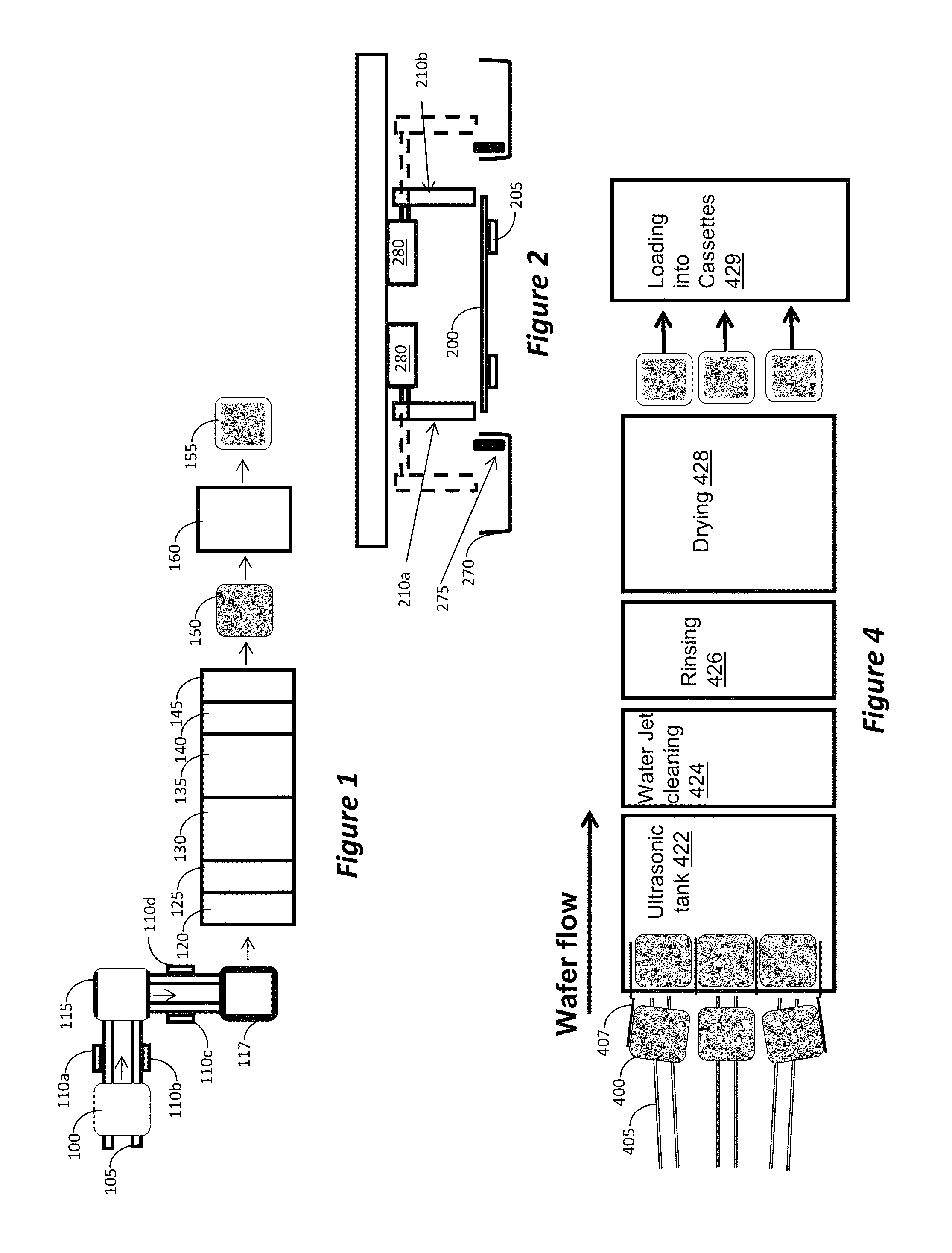
[0046]According to another example, the same masking approach as disclosed above is used; however, a laser is used to burn off the organic masking material, setting the metal layer above it loose. Then, the loose deposited material can be simply blown off or washed away. In this example, the laser should have a wavelength in the range that silicon is transparent to. For example, silicon is transparent to infrared light with wavelengths above about 1.1 micrometres. Thus, by using a laser at, e.g., 1090 nanometer, the system is able to remove metal which is deposited over inkjet mask, without melting the metal nor damaging the underlying silicon. The latter was confirmed by photo luminescence analysis. The advantage of this method is that it does not reduce the cell area that collects the light, does not generate silicon particles, does not re-sputter removed metal, and does not damage the silicon that lies underneath the laser processed area. The laser may be used at power range of 3...

example iii

[0049]Another example is provided herein, which is particularly beneficial for fabrication of the back contact in silicon-based solar cells. FIGS. 8A-8E schematically illustrate a process for forming the back contact of a silicon-based solar cell, according to one embodiment. In FIG. 8A, contact 880 is formed on the backside of solar cell 800. Contact 880 may be made of, e.g., silver, using conventional technology, such as silk screening of silver paste, or inkjet printed with a conductive and solder able ink. In FIG. 8B, a mask 883 is inkjet printed over the silver contact 880, using the printing technique described in the above examples. Then the cell is transferred to a deposition system and an insulating layer 885, such as silicon oxide or silicon nitride, is deposited over the entire backside of the cell 800, as shown in FIG. 8C. The cell is then transferred to a lifting station, such as that described in Examples I or II above, and the mask 883 is removed, together with the in...

example iv

[0050]FIGS. 9A-9J illustrate an example of an embodiment for fabricating interdigitated back contact solar cell. Such a solar cell is advantageous in that it has no metal contacts on the front surface thereof, thus having larger surface for collecting sunlight. In FIG. 9A, a mask 980a is formed on the backside of the solar cell 900. The mask is inkjet printed using any of the methods described above. Then, the backside of the wafer is doped, e.g., n-type, using any conventional method, such as diffusion, ion implant, etc., thus creating doped regions 992, as shown in FIG. 9B.

[0051]In FIG. 9C mask 980a has been removed using any of the lifting methods described above, and mask 980b is inkjet to cover the areas doped in the previous step. In order to properly align mask 980b, according to one embodiment during printing of mask 980a, fiduciary elements are printed in addition to the removable mask 980a. The fiduciary elements are printed using masking fluid that is not soluble during t...


PUM

PropertyMeasurementUnit
wavelengthsaaaaaaaaaa
poweraaaaaaaaaa
areasaaaaaaaaaa

Abstract

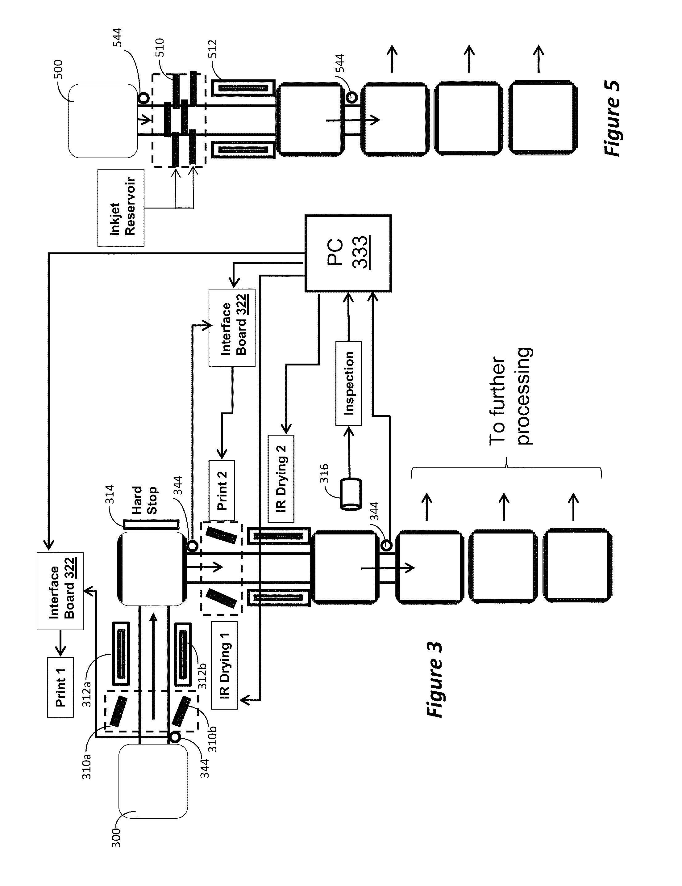
Disclosed are methods and apparatus for masking of substrates for deposition, and subsequent lifting of the mask with deposited material. Masking materials are utilized that can be used in high temperatures and vacuum environment. The masking material has minimal outgassing once inside a vacuum chamber and withstand the temperatures during deposition process. The mask is inkjeted over the wafers and, after deposition, removed using agitation, such as ultrasonic agitation, or using laser burn off.

Description

RELATED CASES[0001]This application claims priority benefit from U.S. Provisional Application Ser. No. 61 / 428,174, filed Dec. 29, 2010; U.S. Provisional Application Ser. No. 61 / 487,679, filed May 18, 2011; and U.S. Provisional Application Ser. No. 61 / 493,948, filed Jun. 6, 2011, the disclosures of all of which are incorporated herein by reference in its entirety.BACKGROUND[0002]1. Field[0003]This disclosure relates to semiconductor fabrication, such as, fabrication of solar cells, and, more specifically, to masking and unmasking of substrates during deposition process.[0004]2. Related Art[0005]During a deposition process, e.g., physical vapor deposition (PVD), chemical vapor deposition (CVD), etc., different materials, such as metals, dielectrics, etc., are deposited on the substrate surface. Often, some areas on the substrate need to remain free of deposition. These areas may include, but not limited to, substrate edges, lines, or various size zones within the substrate.[0006]The s...

Claims


Application Information

Patent Timeline
Patent Type & Authority Patents(United States)
IPC IPC(8): B05C3/00B65G37/00H01L21/00H01L25/00B65G47/12B05D1/18B05C19/02
CPCB05D1/322Y02E10/50C23C16/042H01L31/1876C23C14/042B05D1/327Y02P70/50
Inventor BERGER, ALEXANDER J.BLUCK, TERRYSHAH, VINAYHUANG, JUDYJANAKIRAMAN, KARTHIKNGUYEN, CHAU T.STUMBO, GREG
Owner INTEVAC
Why Eureka
Try Eureka