
Miniaturized radio-frequency identification tag and microstrip patch antenna thereof

a microstrip patch and radio frequency identification technology, applied in the direction of resonant antennas, radiating elements, instruments, etc., can solve the problems of unstable identification rate of common tags at different positions, inconvenient mass production, and inability to ensure electric power required by driving rfit chips, etc., to achieve stable identification rates in different positions and avoid lowering antenna performance.

Active Publication Date: 2014-03-25
XERAFY SINGAPORE PTE LTD
View PDF13 Cites 2 Cited by
  • Summary
  • Abstract
  • Description
  • Claims
  • Application Information

AI Technical Summary

Benefits of technology

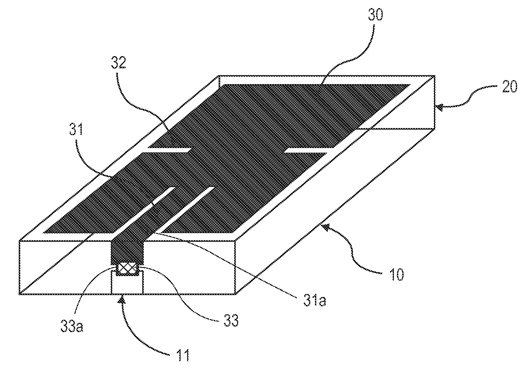
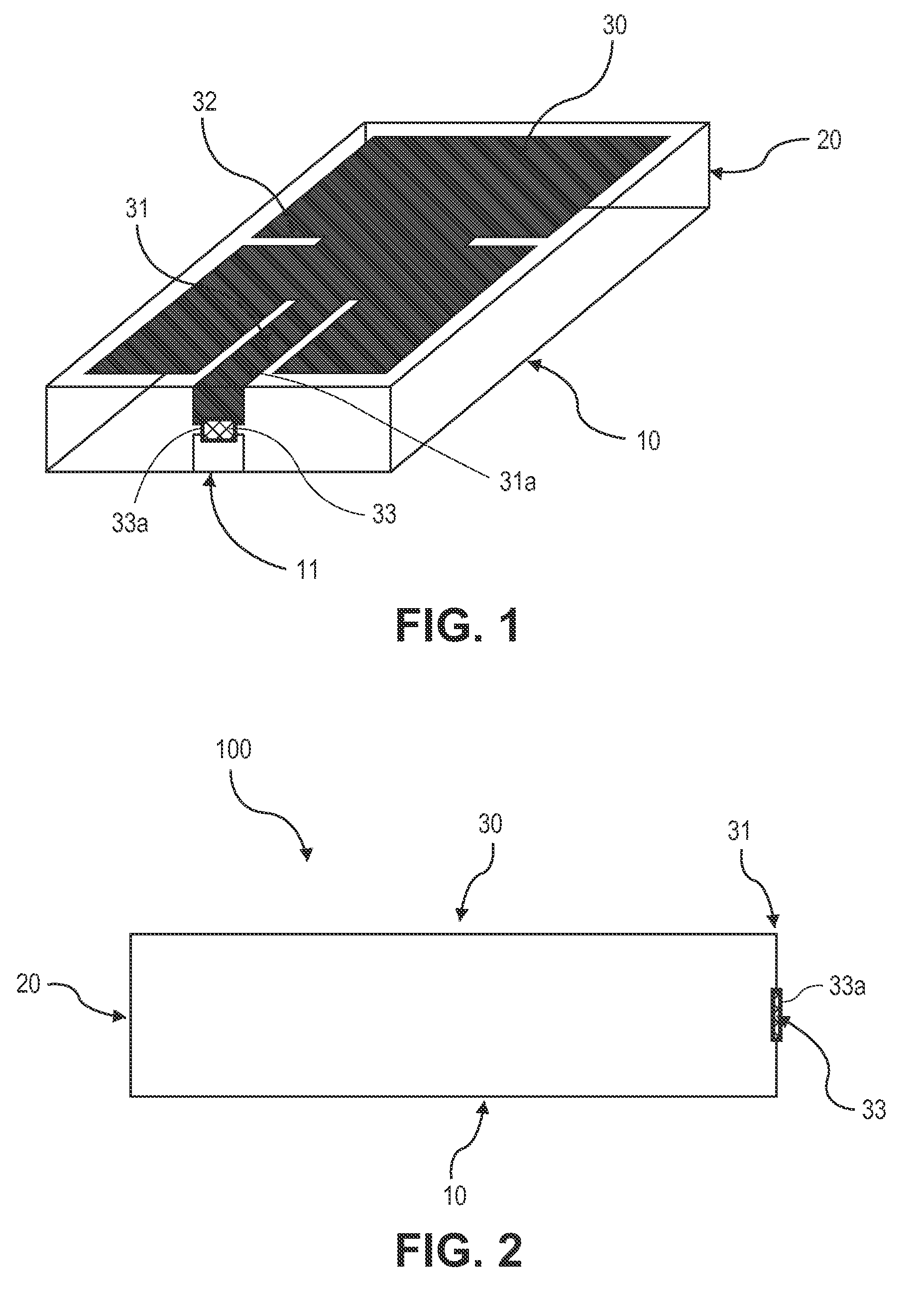
[0012]To solve the problem above, the aim of the present invention is to provide a miniaturized RFIT antenna, wherein when the miniaturized RFIT of the microstrip patch antenna using a metal body as the ground of the antenna is attached to the metal body, the performance of the antenna will not be lowered, the identification rates in different positions will be stable, and an RFIT making use of the said antenna.
[0013]Furthermore, the aim of the present invention is to provide a miniaturized RFIT antenna, wherein the power supply part is designed to be microstrip and connected directly with a radiation part; for the connection with the radio frequency chip, the position of the power supply part is design to be in any position, the top, bottom or side of the dielectric medium, where connection can be conducted easily, and an RFIT making used of the said antenna.
[0015]Furthermore, the aim of the present invention is to provide a microminiaturized metal-attaching type RFIT antenna, wherein the manufacturing process of the antenna is comparatively simple, manufacturing cost is relatively low and various frequency bands can be produced with simple methods, and an RFIT making use of the said antenna.
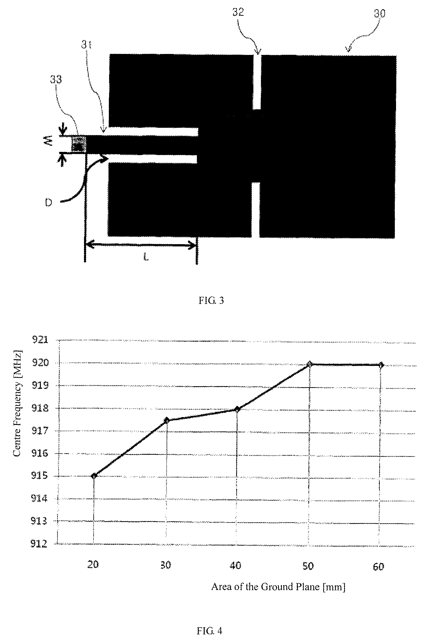
[0024]According to the miniaturized RFIT antenna based on the present invention above, the length and width based on the radiation part or bottom surface, the length and width of the slit formed on the radiation part, have the advantage of easy impedance matching with the matching of the ideal resonant frequency and various tag chips as the purpose; furthermore, on the power supply mode, micropstrips are used so that the power supply part can be set in any position, the top, bottom or side face, according to the application environment; furthermore, the embedded chip is not “protruding”, so that it is not easily damaged by the external environment. Due to these advantages, the antenna can be formed in a simple Print form, thus realizing such advantages as mass production, low production cost and use in the miniaturized metal-attaching application field.
[0025]The miniaturized RFIT antenna based on the present invention, as the tag product attached to metals, of which the performance will not be lowered and identification rate will keep stable even attached to metals of various forms; due to simple production method, various forms can be realized, so that the antenna has the advantage of being easily applicable to wide application fields.

Problems solved by technology

When the antenna used on the tag is attached to the surface of metal materials, the identification rate of common tags is unstable at different positions.
Generally, a dipole antenna brought near a metal body cannot radiate electromagnetic waves, while, according to the reflected wave on the metal surface, the electric power required by the driving of RFIT chip cannot be ensured.
However, the application of tag antennas made in this way in practical commonly-used products brings some inconvenience.
In different environments, such as different metal bodies and different shapes, there are different requirements for such tag antennas, which is not advantageous for mass production.
Furthermore, the use environments may cause damage to tags, especially when increasing of the thickness and size, which is not advantageous for miniaturization.
Usually, although the manufacturing of the microstrip patch antenna is relatively easy, the tag antenna made seems a little bigger due to the half-wave design on resonant frequency, which becomes the disadvantage.
Compared to the microstrip patch antenna, the quarter-wave design of the PIFA antenna on resonant frequency makes miniaturization possible, but the consequent problem is that manufacturing becomes complex.
In view of this, provision of an RFIT and an antenna thereof to solve the problem above has become a technical problem in need of urgent solution in the field.

Method used


Image

  • Miniaturized radio-frequency identification tag and microstrip patch antenna thereof
  • Miniaturized radio-frequency identification tag and microstrip patch antenna thereof
  • Miniaturized radio-frequency identification tag and microstrip patch antenna thereof

Examples


Embodiment Construction

[0033]The present invention will be further illustrated hereinafter in conjunction with the specific embodiments. The technicians in the field can easily understand other advantages and functions of the present invention according to the contents disclosed by the description. The present invention can also be implemented or applied through other different embodiments. Various modifications or changes can be made to the details of the description without deviation from the aims of the present invention according to different views and applications.

[0034]Radio frequency identification technology is a technology wherein objects are identified by attaching an electric tag onto various objects and identifying the inherent ID of the objects through wireless means. The radio frequency identification system applies to various bands in the range from the 125 kHz frequency band to 5.8 GHz microstrip according to the applicable fields.

[0035]Recently, in fields, including logistics circulation ...


PUM


Abstract

A miniaturized Radio Frequency Identification (RFID) tag and a microstrip patch antenna thereof are provided. The miniaturized RFID tag includes: a chip, substrate and a microstrip patch antenna. The microstrip patch antenna is attached to a surface of the substrate and includes a power supply part and a radiation part connected with each other. The power supply part is connected with the chip through a microstrip line. Two sides of the radiation part are provided with at least one slit which has the length of one-half wavelength and enables the tag product to be used normally within a range of shorter than one-half normal wavelength. A maximum point and a minimum point are generated in the radiation part simultaneously, so the tag can be used normally without influencing the performance, even when the tag is in contact with any metal surface. The tag can be miniaturized at the same time.

Description

CROSS-REFERENCE TO RELATED APPLICATION[0001]This application claims foreign priority to and is a National Stage Application of International Application No. PCT / CN2010 / 000429, entitled, “MINIATURIZED RADIO-FREQUENCY IDENTIFICATION TAG AND MICROSTRIP PATCH ANTENNA THEREOF,” filed Apr. 2, 2010, which claims priority to Chinese Application No. 201010023038.2, entitled, “MINIATURIZED RADIO-FREQUENCY IDENTIFICATION TAG AND MICROSTRIP PATCH ANTENNA THEREOF,” filed Jan. 20, 2010, which are both hereby incorporated by reference in their entirety.FIELD OF THE INVENTION[0002]The present invention relates to a miniaturized radio frequency identification tag (RFIT) and an antenna thereof, and more specifically to an RFIT and an h antenna thereof that can be used on metal surface.BACKGROUND OF THE INVENTION[0003]Radio Frequency Identification, which is a non-contact automatic identification technology, identifies target objects and obtains related data automatically through RF signals, featuring...

Claims


Application Information

Patent Timeline
Patent Type & Authority Patents(United States)
IPC IPC(8): H01Q1/36H01Q1/38G06K19/00G06K19/06
CPCH01Q1/2225H01Q9/0442G06K19/077H01Q1/22H01Q13/08
Inventor LIU, ZHIJIA
Owner XERAFY SINGAPORE PTE LTD
Learn More