
Single loop multistage fuel production

a fuel production and single-loop technology, applied in the direction of gaseous fuels, metal/metal-oxide/metal-hydroxide catalysts, chemical production, etc., can solve the problems of unsatisfactory cold temperature performance of gasoline and consequently be reduced, and achieve high reactor utilization efficiency and enhance the conversion of synthesis gas

Active Publication Date: 2014-04-01
BLUESCAPE CLEAN FUELS LLC
View PDF19 Cites 11 Cited by
  • Summary
  • Abstract
  • Description
  • Claims
  • Application Information

AI Technical Summary

Benefits of technology

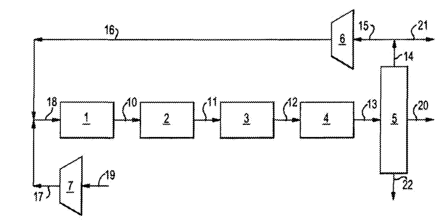
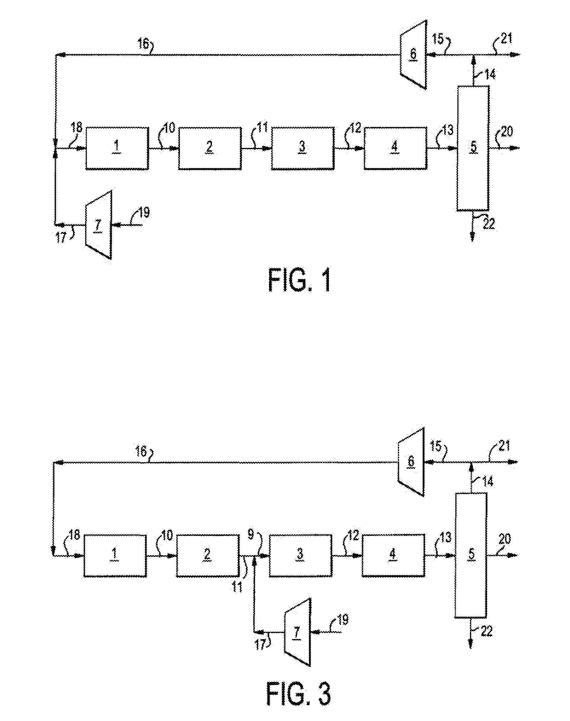
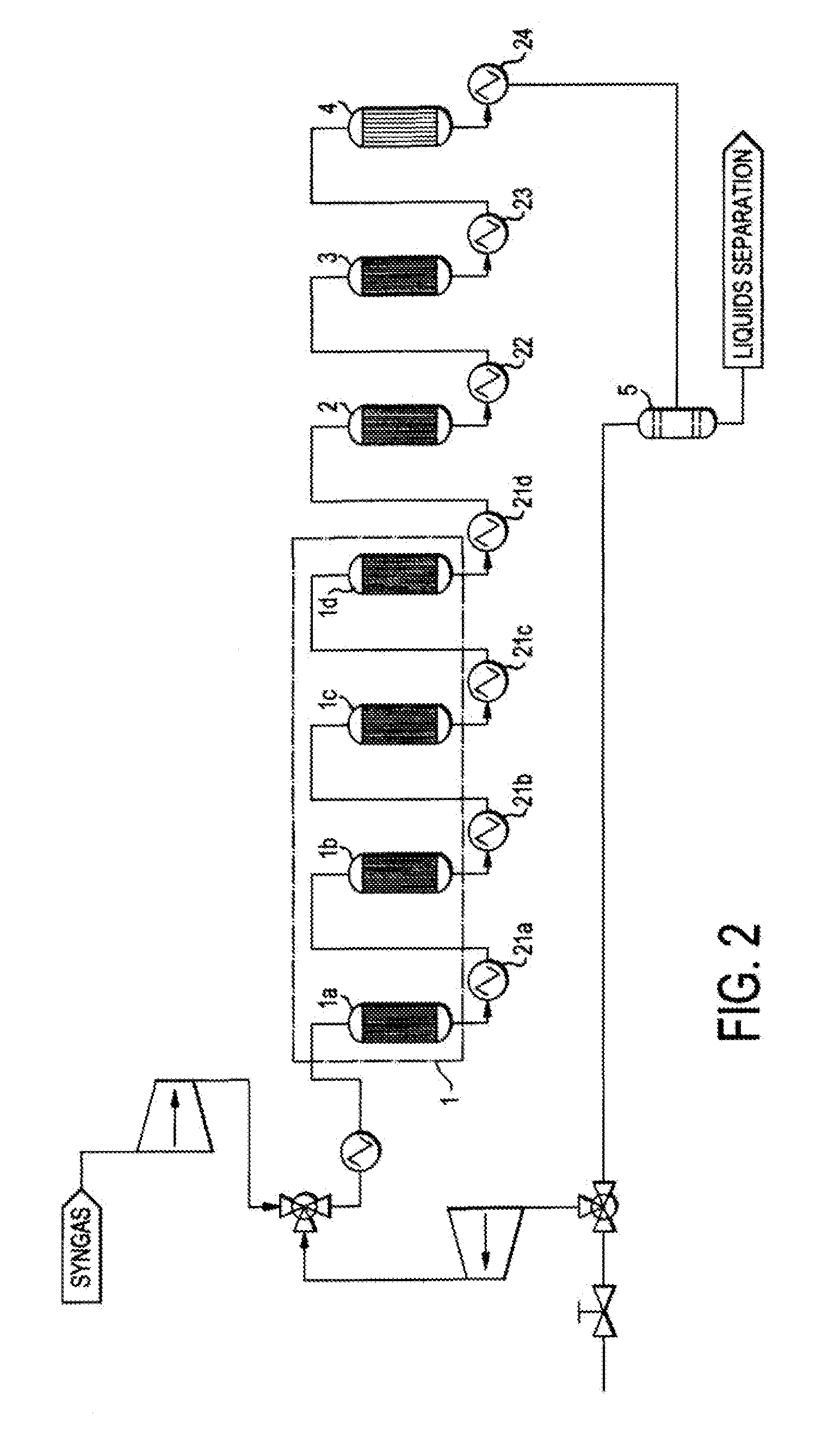
This patent describes a new process to make transportation fuels directly from synthesis gas containing carbon monoxide, carbon dioxide, and hydrogen. The process involves four sequential catalytic stages with intermediate heat exchange, but without interstage separation. The unreacted gases from the fourth stage are recycled to the first stage, which enhances the conversion of the synthesis gas. The recycle also acts as a heat sink for the highly exothermic reactions involved in each stage. This process operates at high pressure, resulting in high reactor utilization efficiencies. Unlike previous methods, this invention uses high concentrations of carbon monoxide in the recycle gas, which allows for the use of a variety of catalysts. The hydrotreating reactions in the fourth stage are carried out in the presence of high concentrations of carbon monoxide, which is commonly taught to poison catalysts.

Problems solved by technology

In the Mobil MTG process, durene is produced in enough quantities to result in undesirable cold temperature performance of the gasoline and must consequently be reduced.

Method used


Image

  • Single loop multistage fuel production
  • Single loop multistage fuel production
  • Single loop multistage fuel production

Examples


example 1

[0039]In this example, R-1, R-2 and R-3 were used in-line with R-4 off-line to provide a base case for comparison to the beneficial effect of R-4 hydrotreating. R-1 contained 400 g of copper / zinc oxide / alumina (Katalco 51-9) catalyst, R-2 contained 200 g of gamma-alumina (SAS 250) and R-3 contained 200 g of the zeolite ZSM-5. The synthesis gas was composed of the following flows: 6130 scm3 H2. 2200 scm3 CO, and 500 scm3 Ar. Temperatures were as follows:[0040]R-1, 280° C.; R-2, 385° C.; and R-3, 410° C. The pressure was 50 atmospheres at the outlet with minor pressure drop through the reactors. Liquid was collected in the separator at the rate of 6-7 g / h hydrocarbon together with by-product water. The hydrocarbon was analyzed by IR and GC-MS. The IR was used to confirm the identity of the components in the sample. The GC-MS results are shown in FIG. 4.

example 2

[0041]In this example, R-1, R-2, R-3 line up, flows, temperatures and pressure were the same as in Example 1 and R-4 was added containing 50 g of catalyst-A (Criterion KL6515, a 60% Ni on alumina catalyst) held at 130° C. Liquid was collected in the separator at the rate of 7.04 g / h hydrocarbon and by-product water. The hydrocarbon was analyzed by IR and GC-MS. The GC-MS results in FIG. 5(a) show that the durene content was significantly reduced compared to Example 1, which did not utilize R-4.

example 3

[0042]In this example the reactor line-up and pressure were the same as in Example 2, however, the catalyst in R-4 was 50 g of catalyst-B (Alfa Aesar 45579, a cobalt molybdate on alumina) held at 140° C. Liquid was collected in the separator at the rate of 7.24 g / h hydrocarbon and by-product water. The hydrocarbon was analyzed by IR and GC-MS. The GC-MS results in FIG. 5(b) show that the durene content was significantly reduced compared to Example 1, which did not utilize R-4.


PUM

PropertyMeasurementUnit
freezing pointaaaaaaaaaa
melting pointaaaaaaaaaa

Abstract

Synthetic fuels are produced from synthesis gas in a four-stage reactor system with a single recycle loop providing the requisite thermal capacity to moderate the high heat release of the reactions and to provide the reactants and reaction environments for the efficient operation of the process. The first stage converts a portion of the synthesis gas to methanol, the second stage converts the methanol to dimethylether, the third stage converts the methanol and dimethylether to fuel and the fourth stage converts the high melting point component, durene, and other low volatility aromatic components such as tri- and tetra-methylbenzenes to high octane branched paraffins.

Description

FIELD OF THE INVENTION[0001]This invention relates to a new process to directly produce transportation fuels, such as gasoline, jet fuel and diesel from synthesis gas containing principally carbon monoxide, carbon dioxide, and hydrogen.BACKGROUND OF THE INVENTION[0002]The prior art describes several alternatives to produce gasoline and distillate from synthesis gas that do not anticipate the present invention of four reaction stages with an overall recycle loop to produce commercial quality fuels. Chang et al (U.S. Pat. No. 3,894,102) and Zahner et al (U.S. Pat. No. 4,011,275) propose that synthesis gas be passed over methanol producing catalyst with an acid component activity to convert methanol to dimethylether and then feeding this intermediate mixed product to a fuel producing stage with recycle of light components to mix with the intermediate mixed product feed.[0003]In another example, Chang et al (U.S. Pat. No. 4,076,761) use synthesis gas produced from coal, shale and / or res...

Claims


Application Information

Patent Timeline
Patent Type & Authority Patents(United States)
IPC IPC(8): C07C1/04
CPCC07C1/041C10G2300/1022B01J2219/0004C10G2400/02C10G2300/4081B01J8/0449C10G45/58C10G3/42C10G2300/4025C10G2400/08C10G3/49C10G2300/304C10G2400/04C10G2400/30Y02P30/20C07C41/09C10G45/60C10G2/32C10G2/33C10G2/331C10G2/332C10G3/46C10G3/48C07C29/151Y02P20/52C07C31/04C07C43/043C10G2/00C10L1/02C07C2/00C10L3/08B01J23/72
Inventor FANG, HOWARD L.BEN-REUVEN, MOSHEBOYLE, RICHARD E.KOROS, ROBERT M.
Owner BLUESCAPE CLEAN FUELS LLC
Learn More