Imaging or communications system utilizing multisample apodization and method

a multi-sample, imaging or communication system technology, applied in the field of array-based imaging and sensing, can solve the problems of imperfect solution, affecting the quality of imaging, and almost never true for medical ultrasound imaging, and achieve the effect of facilitating optimization of contrast resolution of a broadband signal

Active Publication Date: 2014-06-03
UNIV OF VIRGINIA ALUMNI PATENTS FOUND
View PDF1 Cites 25 Cited by
  • Summary
  • Abstract
  • Description
  • Claims
  • Application Information

AI Technical Summary

Benefits of technology

[0044]In at least one embodiment, each tap weight is calculated by minimizing a ratio of energy outside of a cyst being imaged by an instantaneous spatial response calculated for the tap for which the filter weight is being calculated, relative to the energy inside of the cyst.
[0062]In at least one embodiment, each filter weight is calculated by minimizing a ratio of energy outside of a cyst being imaged by an instantaneous spatial response calculated for the tap for which the filter weight is being calculated, relative to the energy inside of the cyst.
[0081]A method of facilitating optimization of contrast resolution of a broadband signal by a system, the system including multiple channels, and finite impulse response filters having multiple taps connected to the multiple channels is provided, including: storing sets of pre-calculated tap weights in computer memory, each set of lap weights providing a tap weight for each lap of each of the finite impulse response filters; and displaying at least one of: at least a portion of the sets of tap weights or at least one indicator for selecting one of the sets of tap weights.

Problems solved by technology

This is almost never true for medical ultrasound imaging and is dubious for many other applications.
Thus these conventional windows, though widely used, are known to be an imperfect solution.
Furthermore, these windows are further limited because they are derived for a single operating frequency and modern array based imaging and communications systems almost entirely operate in a broad band mode.
Furthermore, FD filters can only achieve image quality that is equivalent to the use of continuously varying focal delays (i.e. no delay quantization).
The application of such continuously varying delays will not achieve the optimal image quality (contrast and resolution) possible for a given system.

Method used


Image

  • Imaging or communications system utilizing multisample apodization and method
  • Imaging or communications system utilizing multisample apodization and method
  • Imaging or communications system utilizing multisample apodization and method

Examples


example 1

Comparing the FIR (Non-Robust) and the DAS Beamformers

[0249]A 64 element 150 μm pitch 1D linear array operating at 6.5 MHz and 75% fractional bandwidth was simulated, using DELFI, a custom ultrasound simulation tool (e.g., see Ellis et al., “A Spline Based Approach for Computing Spatial Impulse Responses”, IEEE Trans. on Ultrason., Ferroelect., Freq. Contr., vol. 54, no. 5, pp. 1045-1054, 2007, which is hereby incorporated herein, in its entirety, by reference thereto) that can be downloaded from the Mathworks MATLAB (The Mathworks, Inc. Natick, Mass.) file exchange website (mathworks.com / matlabcentral). All calculations were performed on an IBM Intellistation Z Pro (Processor speed 2.80 GHz, 4.00 Gb RAM. IBM Corporation, Armonk, N.Y.).

[0250]Instantaneous spatial responses were calculated in a 2D plane, azimuth and range, with a particular receive focus. Testing was performed to show the ability of the tap weights (QCLS) algorithm to produce optimal responses when using different FI...

example 2

Performance of the Non-Robust FIR Beamformer in the Presence of Phase Aberration

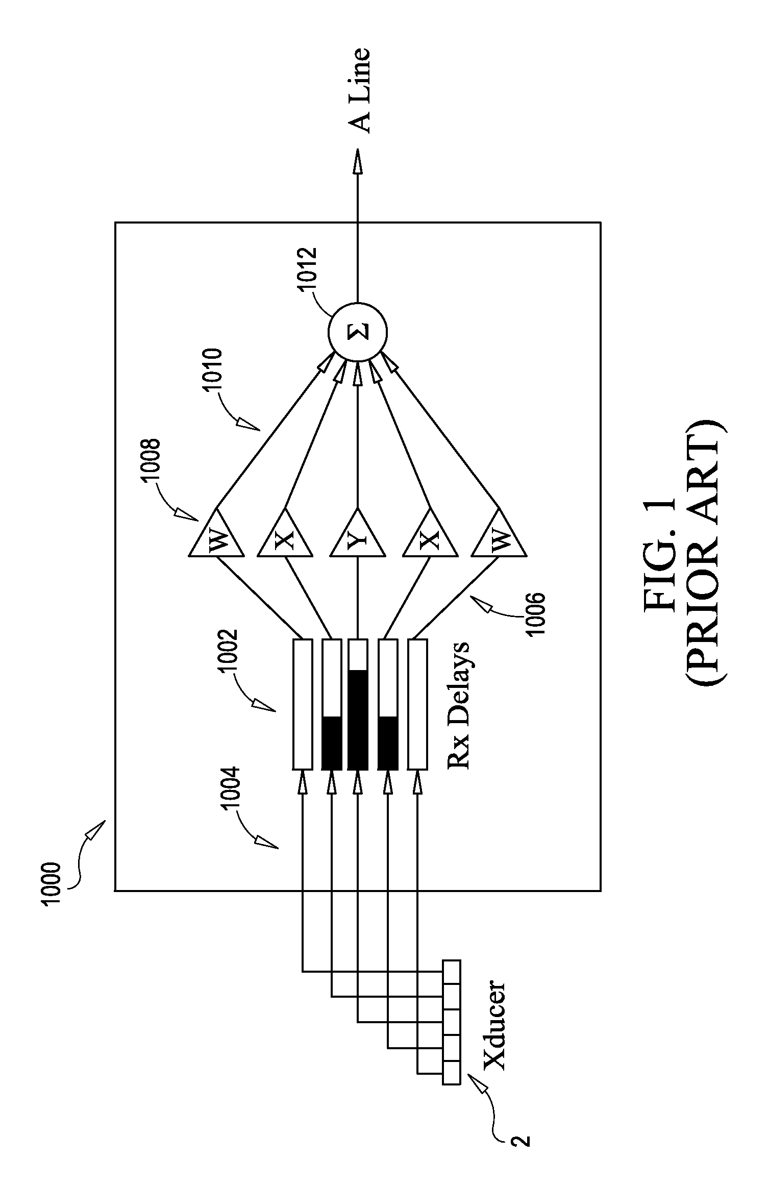
[0263]Receive channel focal delays 1002 in the prior art DAS beamformer 1000 are calculated assuming a propagation speed of sound in tissue. Conventional systems assume a uniform sound velocity of 1540 m / s, however actual sound velocities in human tissue vary between human subject and tissue type. Spatial variations from the assumed sound speed cause wavefront distortion, amplitude variation, and phase variation of the ultrasound beam. These distortions or phase aberrations adversely affect the quality of in vivo images. Phase aberration will distort the DAS beamformer's 1000 ISR, reducing the contrast and resolution of the output image.

[0264]Recent literature indicates that phase aberrations in the human breast can be modeled as a nearfield thin phase screen characterized by a root mean square (RMS) amplitude strength of 28 ns and a full-width at half-maximum (FWHM) correlation length of 3.6 mm. A serie...

example 3

Application to an Ultrasonic Scanning System

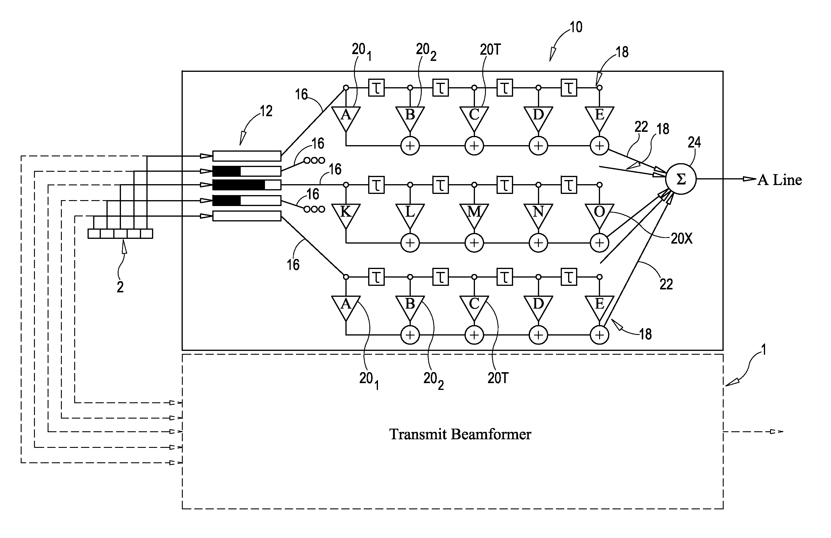
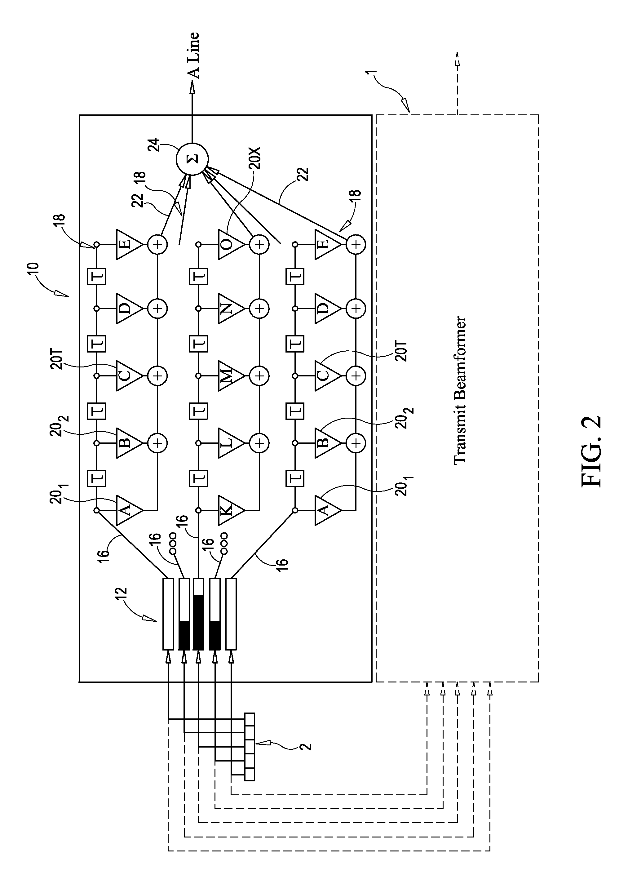
[0271]An embodiment of the beamformer 10 according to the present invention was applied to an existing ultrasound scanner to improve the spatial response characteristics thereof. The ultrasonic scanner system used was the Ultrasonix Sonix RP ultrasound scanner (Ultrasonix Medical Corp., Richmond, BC, Canada). The Sonix RP system has a software development kit (SDK) named TEXO that enables low level scanner control with the ability to acquire single channel RF data sampled at 40 MHz with 12 bit precision. The present inventors created an interface to the TEXO SDK using PYTHON™ programming language that allowed creating of customized pulse sequences without the need to recompile the system C code. Utilizing the PYTHON™ interface with the TEXO SDK a full set of synthetic receive aperture data was acquired from a 64 element transmit aperture and 64 element receive aperture in fractions of a second. In order to measure the 2D ISR required for t...


PUM


Abstract

Methods, systems and system components for optimizing contrast resolution of an imaging or sensing system utilizing multiple channels of broadband data associated with an array of transducers. Channels or data are filtered by passing the channels of data through finite impulse response (FIR) filters on each channel. The filters each have multiple taps having tap weights pre-calculated as a function of distance of the array from an object that energy is being transmitted to or reflected from. The weights are pre-computed through a deterministic equation based on an a priori system model.

Description

GOVERNMENT RIGHTS[0001]This invention was made with government support under federal grant no. 5R01EB5433 awarded by The National Institutes of Health and U.S. Army Congressionally Directed Research Program Grant No. W81XWH-04-1-0590. The United States Government has certain rights in this invention.CROSS-REFERENCE[0002]This application claims the benefit of U.S. Provisional Application No. 61 / 029,329, filed Feb. 16, 2008, which application is hereby incorporated herein, in its entirety, by reference thereto. This application also claims the benefit of U.S. Provisional Application No. 61 / 049,244, filed Apr. 30, 2008, which application is hereby incorporated herein, in its entirety, by reference thereto.FIELD OF THE INVENTION[0003]The present invention relates to the field of array-based imaging and sensing, and more particularly to optimizing contrast resolution of a beamformer used in such applications.BACKGROUND OF THE INVENTION[0004]The relative weighting of individual channels i...

Claims


Application Information

Patent Timeline
Patent Type & Authority Patents(United States)
IPC IPC(8): G06K9/00
CPCG10K11/346G01S15/8927G01S7/52046G06T2207/20024G06T2207/10132G06T5/002G06T5/009
Inventor WALKER, WILLIAM F.GUENTHER, DRAKE A.OWEN, KEVIN
Owner UNIV OF VIRGINIA ALUMNI PATENTS FOUND
Why Eureka
Try Eureka