Electromechanical transducer and photoacoustic apparatus

a transducer and photoacoustic technology, applied in the field of electromechanical transducers, to achieve the effect of reducing the band width and preventing the degradation and dispersion of sensitivity

Active Publication Date: 2014-07-01
CANON KK
View PDF12 Cites 2 Cited by
  • Summary
  • Abstract
  • Description
  • Claims
  • Application Information

AI Technical Summary

Benefits of technology

[0005]In a case a capacitance type electromechanical transducer is used as a sensor for receiving a photoacoustic wave, when a light for generating the photoacoustic wave is incident on the transducer, a photoacoustic wave is generated in the receiving face of the transducer to cause a noise. In Japanese Patent Application Laid-Open No. 2010-075681, in order to prevent such a situation, the reflection member is arranged just before the receiving face of the capacitance type electromechanical transducer so that the light is not incident on the transducer. As an improvement of the prior art, there is a need to reduce a change of the spring constant of the vibration film constituting the transducer and dispersion of the deformation amounts of the vibration film, to thereby efficiently prevent the degradation and dispersion of sensitivity and the reduction of band width.
[0007]The electromechanical transducer according to the present invention has the stress relaxation layer provided on the vibration film which is a receiving face of the transducer, and has the light reflection layer provided thereon. Accordingly, the receiving face is not affected so much by a stress of the light reflection layer, and accordingly the vibration film resists causing deformation and the like therein. Thereby, the electromechanical transducer having the light reflection layer formed therein can lower the dispersion of its performance, and can receive an elastic wave such as a photoacoustic wave.

Problems solved by technology

In a case a capacitance type electromechanical transducer is used as a sensor for receiving a photoacoustic wave, when a light for generating the photoacoustic wave is incident on the transducer, a photoacoustic wave is generated in the receiving face of the transducer to cause a noise.

Method used


Image

  • Electromechanical transducer and photoacoustic apparatus
  • Electromechanical transducer and photoacoustic apparatus
  • Electromechanical transducer and photoacoustic apparatus

Examples


exemplary embodiment 1

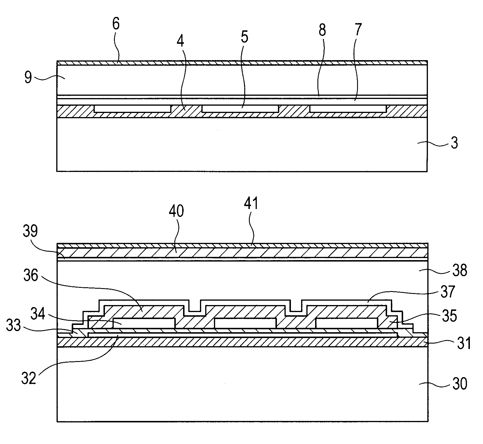
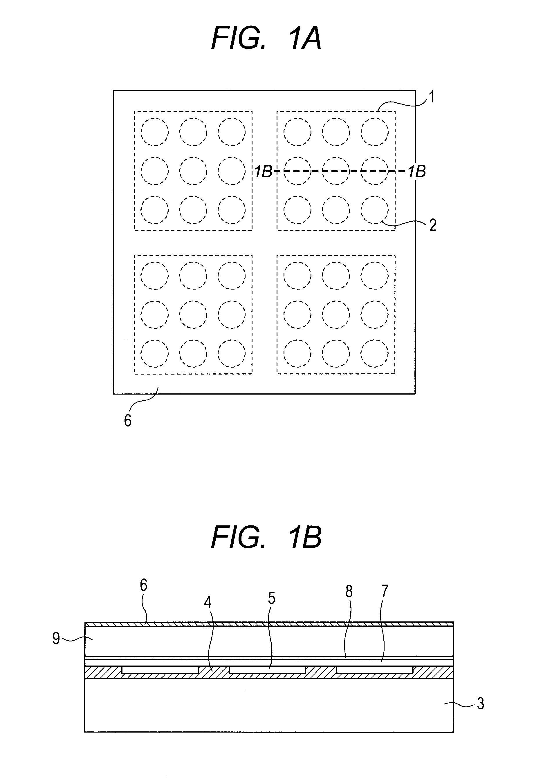
[0024]The structure of the capacitance type electromechanical transducer of Exemplary Embodiment 1 will be described below with reference to FIG. 1A and FIG. 1B. The electromechanical transducer of the present exemplary embodiment has a plurality of elements 1 therein. Although only four elements 1 are provided in FIG. 1A and FIG. 1B, the number of the elements may be any number.

[0025]A cell 2 includes a vibration film 7 of single-crystal silicon having a thickness of 1 μm, a space 5, a vibration film supporting portion 4 which supports the vibration film 7 of the single-crystal silicon having a resistivity of 0.01 Ωcm, and a silicon substrate 3. The silicon substrate 3 has a thickness of 300 μm and a resistivity of 0.01 Ωcm. The shape of the vibration film 7 of the present exemplary embodiment is a circle with a diameter of 30 μm, which may also be a quadrangle, a hexagon or the like. The vibration film 7 of the single-crystal silicon is mainly formed of single-crystal silicon, and...

exemplary embodiment 2

[0028]The structure of the capacitance type electromechanical transducer of Exemplary Embodiment 2 will be described below with reference to FIG. 2. The electromechanical transducer of Exemplary Embodiment 2 has an approximately similar structure to that of Exemplary Embodiment 1. The cell includes an upper electrode 37, a vibration film 36 with a thickness of 1 μm, a space 34, a vibration film supporting portion 35 which supports the vibration film 36, an insulation membrane 33, a lower electrode 32 and a substrate 30. The substrate 30 is a silicon substrate, the vibration film 36 and the vibration film supporting portion 35 are a silicon nitride film, and the upper electrode 37 and the lower electrode 32 are aluminum. An oxide film 31 is arranged between the substrate 30 and the lower electrode 32, and it insulates both of them from each other. When the substrate 30 is a low-resistance silicon substrate or an insulating substrate made from glass or the like, the oxide film 31 need...

exemplary embodiment 3

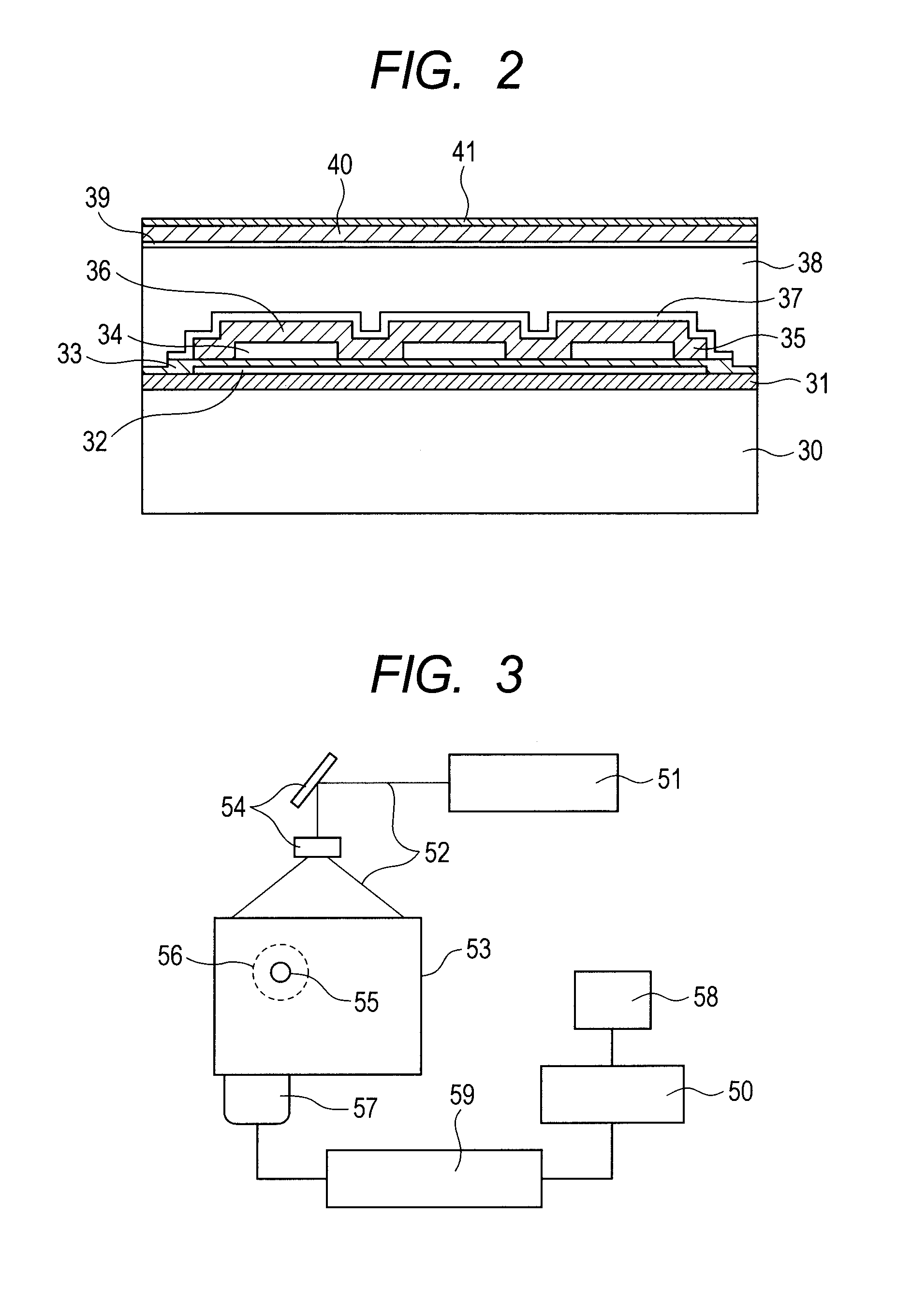
[0033]The electromechanical transducer in each of the above described exemplary embodiments can be used for a photoacoustic apparatus using a photoacoustic imaging technology. The photoacoustic imaging technology is a technology of: firstly irradiating a subject with a pulse light; making an optical absorber absorb the energy of the light which has propagated / diffused in the subject; thereby receiving the generated acoustic wave; and imaging the information in the inner part of the subject by using the received signal for this acoustic wave. Consequently, the photoacoustic apparatus can obtain the information on the profile of optical properties such as the profile of initial pressure generation and the profile of light absorption coefficient in the subject as an image data.

[0034]FIG. 3 illustrates a schematic view of a photoacoustic apparatus to which the present invention can be applied. The photoacoustic apparatus according to the present invention has at least a light source 51,...


PUM


Abstract

The present invention provides an electromechanical transducer which can prevent light from being incident on a receiving face, without deteriorating mechanical characteristics of a vibration film. The electromechanical transducer has at least one cell 2 in which the vibration film 7 containing one electrode 8 out of two electrodes 3 and 8 that are provided so as to interpose a space 5 therebetween is vibratably supported. The electromechanical transducer has a stress relaxation layer 9 formed on the vibration film 7, which has an acoustic impedance matching that of the vibration film 7, and has a light reflection layer 6 formed on the stress relaxation layer 9.

Description

BACKGROUND OF THE INVENTION[0001]1. Field of the Invention[0002]The present invention relates to an electromechanical transducer such as a capacitance type electromechanical transducer which is used as an ultrasonic transducer or the like, and to a photoacoustic apparatus.[0003]2. Description of the Related Art[0004]Conventionally, a micro-mechanical member to be manufactured with a micro-machining technology can be processed in a micro-metric order, and various micro-functional elements are realized by using these members. A capacitance type electromechanical transducer such as CMUT (Capacitive Micromachined Ultrasonic Transducer) using such a technology has been studied as an alternative of a piezoelectric element. Such a capacitance type electromechanical transducer can transmit and receive an acoustic wave such as an ultrasonic wave by using the vibration of a vibration film, and it can easily obtain superior broad band characteristics particularly in a liquid. On the other hand...

Claims


Application Information

Patent Timeline
Patent Type & Authority Patents(United States)
IPC IPC(8): G02B26/08
CPCG01N29/2418B06B1/0292G01H9/00
Inventor TORASHIMA, KAZUTOSHIKASANUKI, YUJI
Owner CANON KK
Why Eureka
Try Eureka