Method and apparatus for a porous electrospray emitter

a technology of electrospray emitter and porous metal, which is applied in the direction of separation process, laboratory glassware, instruments, etc., can solve the problems of inefficient operation, droplets can also contaminate the substrate, add mass/weight and complexity to the system, etc., and achieves increased capillary flow capacity, reduced complexity, and more current

Active Publication Date: 2014-07-22
MASSACHUSETTS INST OF TECH
View PDF15 Cites 17 Cited by
  • Summary
  • Abstract
  • Description
  • Claims
  • Application Information

AI Technical Summary

Benefits of technology

[0009]Porous metal Electrospray emitters have been shown to emit more current than a comparably sized solid externally wetted emitter (e.g., needle), due to the increased capillary flow capacity (e.g., greater flow through volume) provided by the volumetric porosity of the emitter substrate. Porous metal emitters also have the benefit of being a passive, self-regulating capillary supply that reduces complexity over pressure fed capillary systems coupled with the benefit of increased flow through volume that permits the porous metal emitters to emit greater current and provide greater thrust. A typical thrust of a single porous metal emitter operating in the ionic mode can be about 0.05-0.1 μN / μA. Passively fed porous metal Electrospray emitters can emit purely in the ionic regime, which allows for high specific impulse (high ISP) operation and high polydispersive efficiency. Multiple emitters can be grouped to produce a desired amount of current, for example, in space applications. Micro-fabrication techniques can be used to manufacture a single emitter or an array of emitters. Porous metal electrospray emitters can be manufactured using, for example, photolithography and electrochemical etching.

Problems solved by technology

This can translate into inefficient operation.
In ion beam etching, droplets can also contaminate the substrate.
Pressure fed capillary emitters, however, can require pressurization systems (e.g., onboard the spacecraft using the emitters), that adds mass / weight and complexity to the system.
The difficulties in fabricating small, uniform capillaries can pose problems in the miniaturization of needle arrays.

Method used


Image

  • Method and apparatus for a porous electrospray emitter
  • Method and apparatus for a porous electrospray emitter
  • Method and apparatus for a porous electrospray emitter

Examples


Embodiment Construction

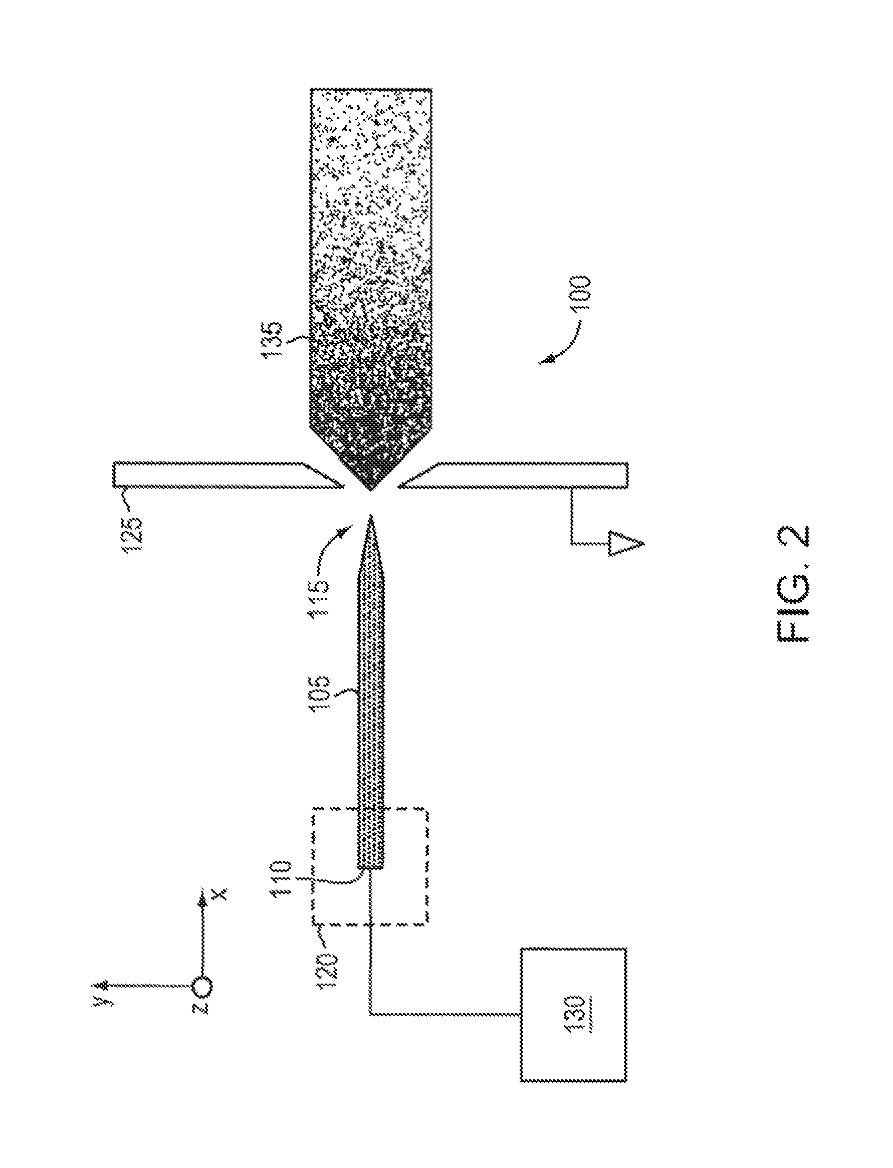
[0067]FIG. 2 is a schematic of an ion source 100, according to an illustrative embodiment of the invention. The ion source 100 includes a body 105 (e.g., an emitter body) that includes a base 110 and a tip 115. The body 105 can be made of a porous metal (e.g., a microfabricated emitter body formed from a porous metal substrate) compatible with an ionic liquid or a room temperature molten salt (e.g., does not react or result in electrochemical decaying or corrosion). The body 105 can be mounted relative to a source 120 of ionic liquid or a source of a room temperature molten salt. The body 105 includes a pore size gradient that decreases from the base 110 of the body 105 to the tip 115 of the body 105, such that ionic liquid can be transported through capillarity (e.g., through capillary forces) from the base 110 to the tip 115. The ionic liquid can be continuously transported through capillarity from the base 110 to the tip 115 so that the ion source 100 (e.g., emitter) avoids liqui...


PUM

PropertyMeasurementUnit
diameteraaaaaaaaaa
diameteraaaaaaaaaa
voltageaaaaaaaaaa

Abstract

An ionic liquid ion source can include a microfabricated body including a base and a tip. The body can be formed of a porous material compatible with at least one of an ionic liquid or room-temperature molten salt. The body can have a pore size gradient that decreases from the base of the body to the tip of the body, such that the at least one of an ionic liquid or room-temperature molten salt is capable of being transported through capillarity from the base to the tip.

Description

CROSS-REFERENCE TO RELATED APPLICATION[0001]This application is a continuation-in-part of, claims the benefit of and priority to U.S. application Ser. No. 13 / 839,064, filed Mar. 15, 2013, which is a continuation-in-part of, claims the benefit of and priority to U.S. patent application Ser. No. 13 / 681,155, filed on Nov. 19, 2012, which is a continuation of, claims the benefit of and priority to U.S. patent application Ser. No. 12 / 990,923, filed on May 3, 2011, which claims the benefit of and priority to PCT application No. PCT / US2009 / 042990 filed on May 6, 2009, which claims the benefit of and priority to U.S. provisional patent Application No. 61 / 050,847 filed on May 6, 2008, the contents of each are incorporated herein by reference in their entirety.[0002]The contents of U.S. Patent Application No. 61 / 695,034, filed Aug. 30, 2012, are incorporated herein by reference in their entirety.[0003]This invention was made with government support under Grant No. DGE-1122374 awarded by the N...

Claims


Application Information

Patent Timeline
Patent Type & Authority Patents(United States)
IPC IPC(8): H01J37/08H01J9/02
CPCH01J9/02H01J37/08H01J2237/0802C25F3/14H01J1/05H01J9/025B01L3/502715H01J49/0445H01J2237/317
Inventor LOZANO, PAULO C.ARESTIE, STEVEN MARK
Owner MASSACHUSETTS INST OF TECH
Why Eureka
Try Eureka