Process for preparing an optical preform

a technology of optical preforms and optical fibers, applied in glass making apparatus, other domestic objects, manufacturing tools, etc., can solve the problems of attenuation of light through fibers, decrease in the distance light can be propagated without being amplified, and complex time-consuming process of manufacturing optical fibers used for communication

Active Publication Date: 2014-08-26
CORNING INC
View PDF9 Cites 8 Cited by
  • Summary
  • Abstract
  • Description
  • Claims
  • Application Information

AI Technical Summary

Benefits of technology

[0014]Additional features and advantages of the invention will be set forth in the detailed description which follows, and in part will be readily apparent to those skilled in the ar

Problems solved by technology

The manufacture of optical fibers used for communications is a complicated and time intensive process involving many steps.
Defects in the core (and materials used to form the core) are critical since these defects can hinder the propagation of the light resulting in loss or attenuation of the light through the fiber and the

Method used


Image

  • Process for preparing an optical preform
  • Process for preparing an optical preform
  • Process for preparing an optical preform

Examples


example 1

Cleaning Step

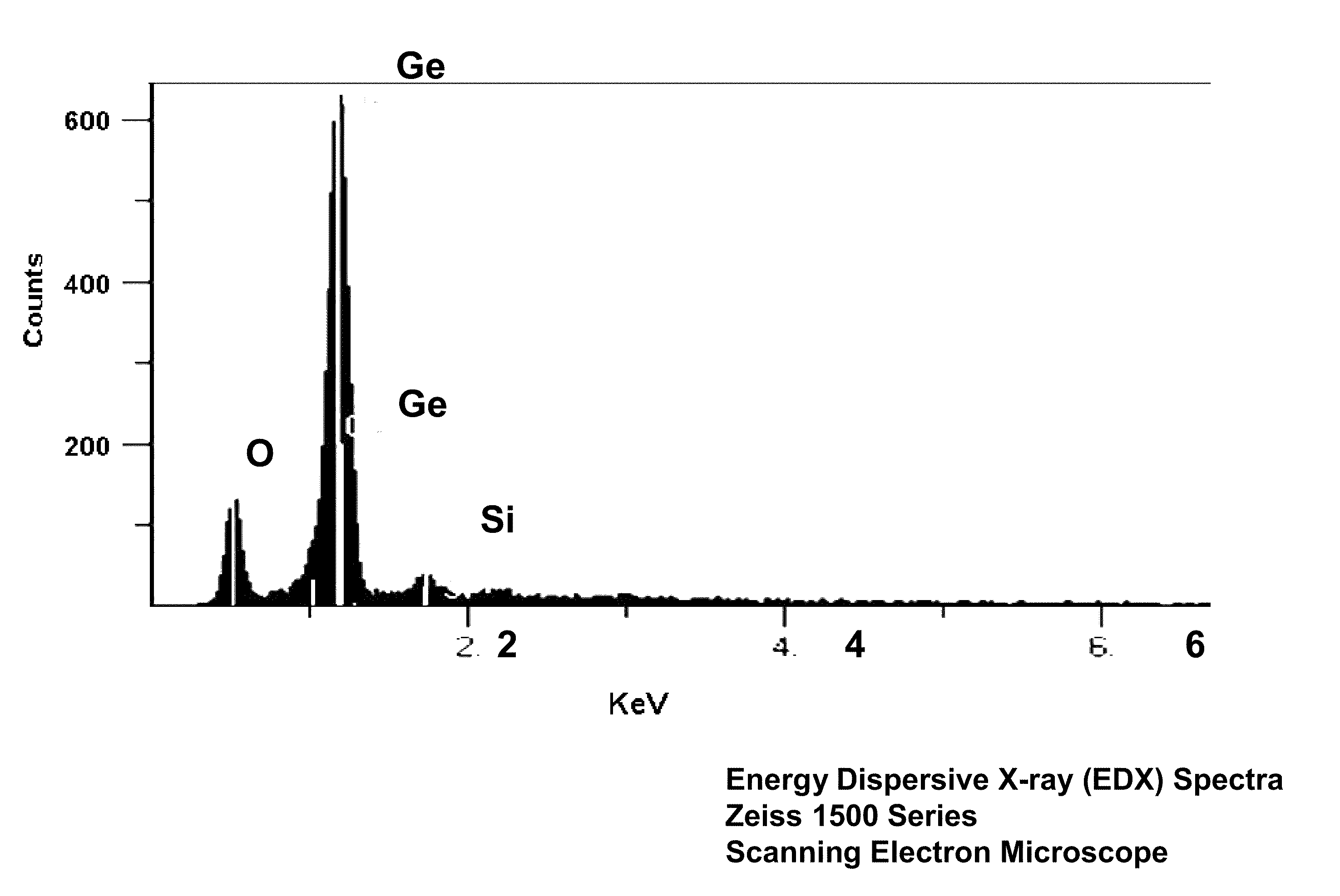
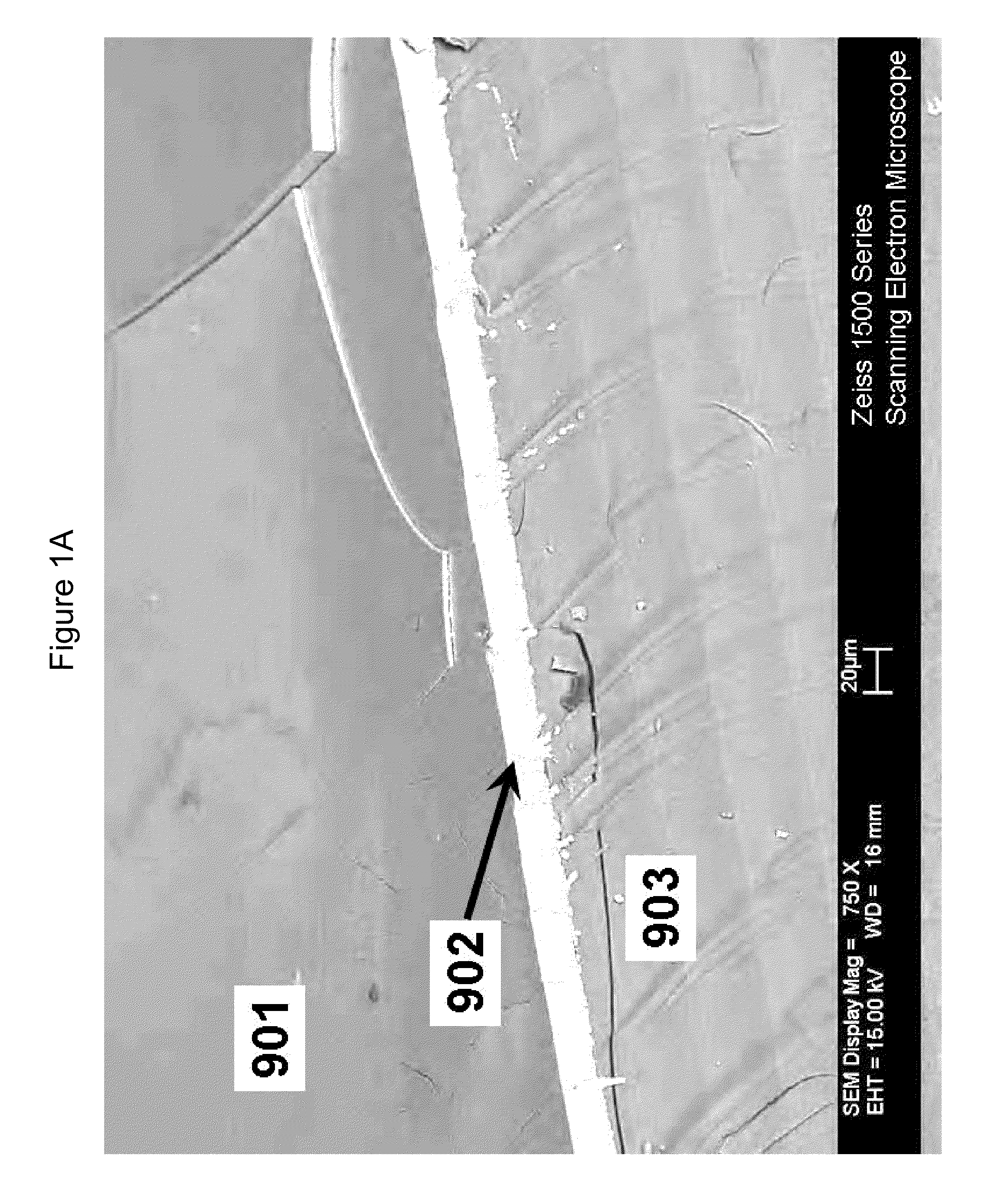
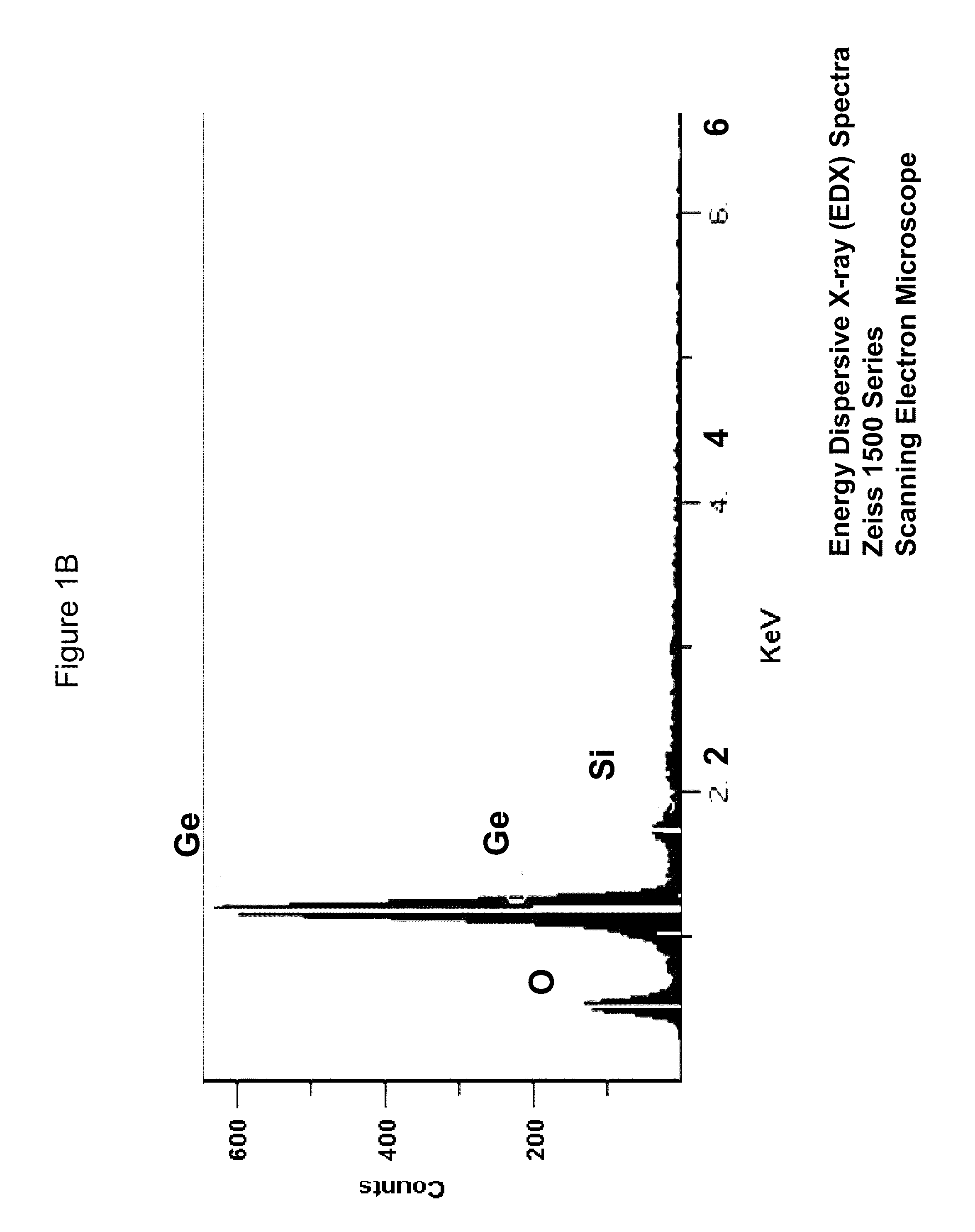
[0058]A silica based, silica preform tube with a large amount of redeposited germanium and germanium oxides (i.e., GeOx) compounds inside the tube (See FIG. 4, left side) was cleaned by using a vapor-phase cleaning process. The vapor-phase cleaning gases comprised carbon monoxide, CO, and chlorine, Cl2, along with a carrier gas of helium. The cleaning gases were passed through the centerline opening 14 as well as around the outside of the preform tube by suspending the preform tube in a quartz-lined furnace for 1 hr at a temperature of 1125° C. Cleaning gas flows into the furnace in SLPM (standard liters per minute) was as follows: 5.0 / 0.50 / 5.0 SLPM of He / Cl2 (He containing 10% by volume CO), respectively, i.e., 4.8% CO and 4.8% Cl2 by volume in helium. The preform (i.e., preform tube) was allowed to cool to room temperature, examined, and showed a clean centerline hole and no evidence of the redeposited GeOx remaining after cleaning (FIG. 4, right hand side). It is als...

example 2

Cleaning Step

[0059]A second silica based, silica preform tube with a large amount of redeposited germanium and germanium oxides (i.e., GeOx) compounds inside the tube was cleaned by using a vapor-phase cleaning process. The vapor-phase cleaning gases comprised carbon monoxide, CO, and chlorine, Cl2 along with a carrier gas of helium. The cleaning gases were passed through the centerline opening 14 as well as around the outside of the tube by suspending the tube in a 6″ diameter quartz-lined furnace for 1 hr at a temperature of 1000° C. Cleaning gas flows into the furnace in SLPM (standard liters per minute) was as follows: 5.0 / 0.50 / 5.0 SLPM of He / Cl2 / (He containing 10% by volume CO), respectively, i.e., 4.8% CO and 4.8% Cl2 by volume in helium. The preform (i.e., preform tube) was allowed to cool to room temperature, examined, and showed a clean centerline hole and no evidence of the redeposited GeOx remaining after cleaning.

example 3

Etching and Cleaning Steps

[0060]A similar set of experiments were run on core preforms having a 2% delta (vs. silica), 36% by weight GeO2 and a parabolic shaped profile as follows. Approximately 7500 grams of GeO2—SiO2 soot having a density of about 0.5 grams / cc were OVD deposited on a 1 meter long by approximately 12 mm diameter removable ceramic rod (substrate rod) to produce the core soot preform. The substrate rod was then removed and the soot preform was placed in a quartz-lined furnace set at 1000° C. then dried in atmosphere comprising helium and approximately 1 volume % each of chlorine and oxygen gases. The soot preform was then sintered in an atmosphere comprising helium to a dense glass preform (with a centerline hole) by lowering it through a hot zone set at approximately 1400° C.-1450° C. The centerline of this preform was then vapor phase etched at this temperature by flowing SF6+O2+He (approximately 90, 100, 500 sccm, respectively) through the centerline hole of the p...


PUM

PropertyMeasurementUnit
Temperatureaaaaaaaaaa

Abstract

A method of preparing an optical preform includes the steps of: a) etching an optical preform to remove a portion of an oxide material deposited on the preform by using a gas comprising an etchant gas containing fluorine at a sufficient temperature and gas concentration to create a redeposited germanium containing compounds contamination such as GeOx in the remaining oxide material; and b) cleaning the etched preform using a cleaning gas containing at least one halogen gas at a sufficient temperature and gas concentration to remove the redeposited germanium containing compound contamination without any substantial further contamination of the remaining deposited oxide material. Preferably the halogen is either chlorine or bromine.

Description

FIELD OF THE INVENTION[0001]This application claims the benefit of priority under 35 U.S.C. §119 (e) of U.S. Provisional Application Ser. No. 61 / 125,984 filed on Apr. 30, 2008.BACKGROUND OF THE INVENTIONTechnology Background[0002]This invention relates to a method of preparing an optical preform. More particularly, the invention relates to a method of removing or reducing unwanted germanium containing compounds produced during the processing of the preform or by exposure to certain environmental conditions.[0003]Optical fibers have acquired an increasingly important role in the field of communications, frequently replacing existing copper wires. This form of transmission is done by sending a beam of light through an optical fiber. Interference with the light beam or its partial loss during transmission must be at a minimum to make the use of optical fibers as a successful communications technology. The manufacture of optical fibers used for communications is a complicated and time i...

Claims


Application Information

Patent Timeline
IPC IPC(8): B29D11/00
CPCC03B37/01466C03B37/01861C03B2201/31C03C15/00C03C23/0075Y02P40/57
Inventor BOOKBINDER, DANA CRAIGLEBLOND, NICOLASYOUNG, JUDITH EILEEN
Owner CORNING INC
Why Eureka
Try Eureka