Heat recovery steam generator and method for fast starting combined cycles

a heat recovery steam and generator technology, applied in the direction of liquid degasification, lighting and heating apparatus, separation processes, etc., can solve the problems of increasing thermal stress and mechanical problems, increasing the amount of moisture content, and causing the greatest damage to the start-stop

Active Publication Date: 2014-09-02
DUFFY THOMAS EDWARD
View PDF1 Cites 43 Cited by
  • Summary
  • Abstract
  • Description
  • Claims
  • Application Information

AI Technical Summary

Benefits of technology

[0021]Shutdowns for a weekends or when steam pressure falls near atmospheric pressure nitrogen is introduced through the high pressure header replacing condensing steam and prevent a vacuum forming and possible air in leakage. For long term storage and for maintenance requiring opening the steam side to air the water in the HRSG would be purged of water by a simple air blowdown of the water side through to circuit drain control valve to a feedwater storage tank. Dry nitrogen would be circulated for sufficient time to purge the air and limit moisture content and ensure 99.6% nitrogen fills the entire waterside of the HRSG to protect it from corrosion.

Problems solved by technology

Operating experience on many proved that start-stops initiated the greatest damage obliging major repairs, replacement and reduced availability in only a few hundred start cycles for many sites.
These requirements thereby result in increasing thermal stresses and mechanical problems for new HRSGs designs still basically using the same designs as the past conventional HRSG configurations.
After a number of start cycles the differential temperatures result in failure of weld joints and tubes.
The use of bypass exhaust stacks are necessary in many installations to allow gradual warm up to prevent failure but are not fast starters and result in efficiency loss.
This is a problem is especially acute during fast starts and shutdowns of high pressure HRSGs even with the Benson HRSG that only solves the thick wall high pressure drum problem by eliminating it entirely.
Thermal shock during starts is a result of rapid differential radial and lengthwise tube expansion eventually causing numerous weld joint cracks, tube cracks and tube buckling with the top and bottom header configurations installed in conventional units.
Particularly vulnerable are the high pressure superheater and reheater header to tube joints and tubes.
Differential temperature of several hundred degrees between the tubes and headers eventually results in fatigue cracking of tube to header welds.
Water condensate from the saturated steam in the tubes collects in the lower headers and interconnecting pipes and has proven difficult to drain prior to the initiation of steam flow.
Another condensate cause of thermal strain is shutdown from high power (trips).
Cracking of lower tube weld joints, header tube bores and distortion of headers and pipes can result from this thermal shock quenching particularly with the high temperatures required for new high pressure CC power plants.
No viable solutions to this damage have been obtained with the conventional HRSGs.
Another source of water quenching damage is interstage attemperation in the high pressure superheater and reheater.
Spraying water into these pipes is another major observed cause of thermal shock damage in many units.
Overspray is a common and difficult to prevent control problem due to lag times and lack of long strait pipe lengths in the interstage pipes between stages.
During starts and other operating modes water spray often impinges on pipe wall quenching them, is then stripped from walls quenching headers and tubes downstream causing cracks.

Method used


Image

  • Heat recovery steam generator and method for fast starting combined cycles
  • Heat recovery steam generator and method for fast starting combined cycles
  • Heat recovery steam generator and method for fast starting combined cycles

Examples


Embodiment Construction

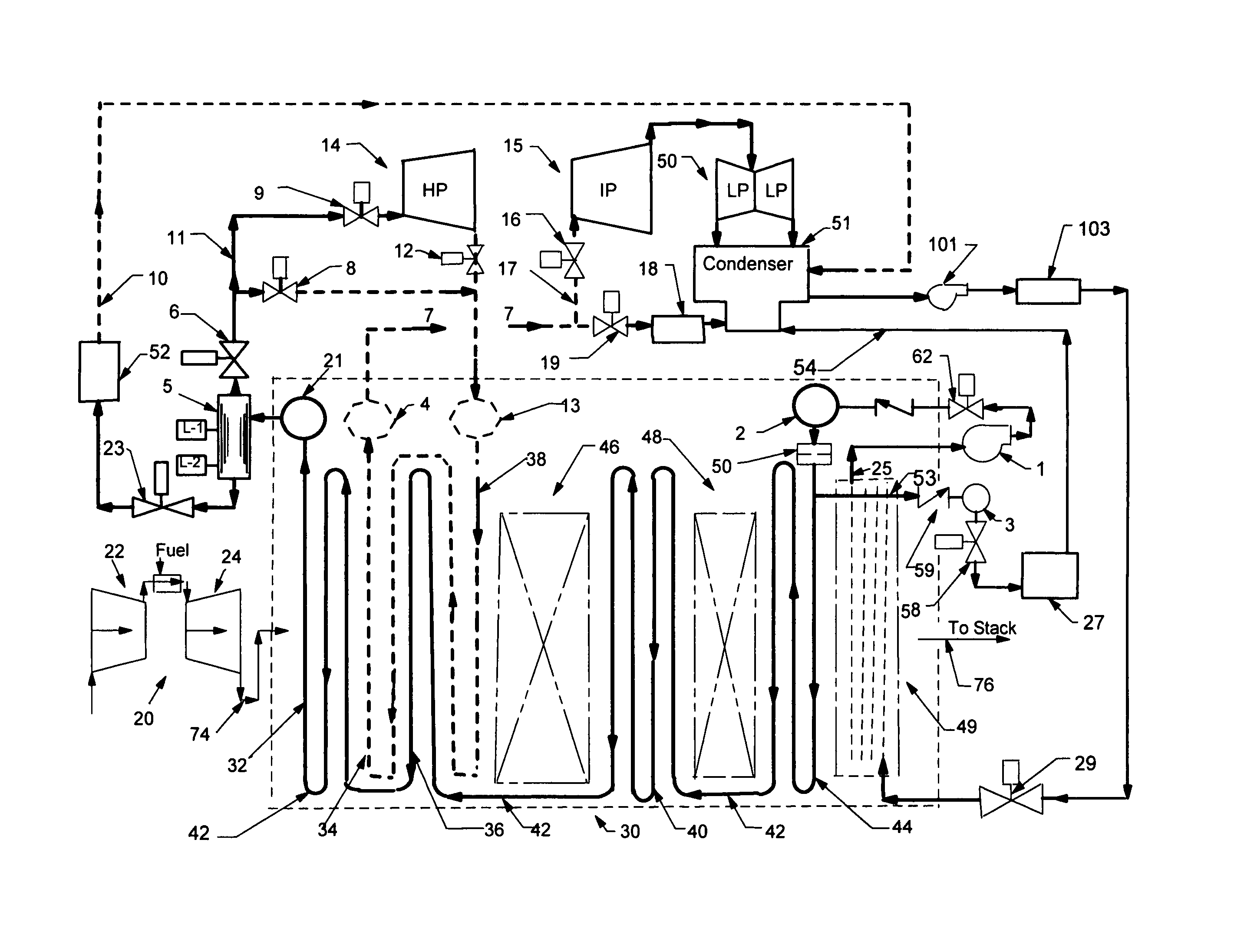
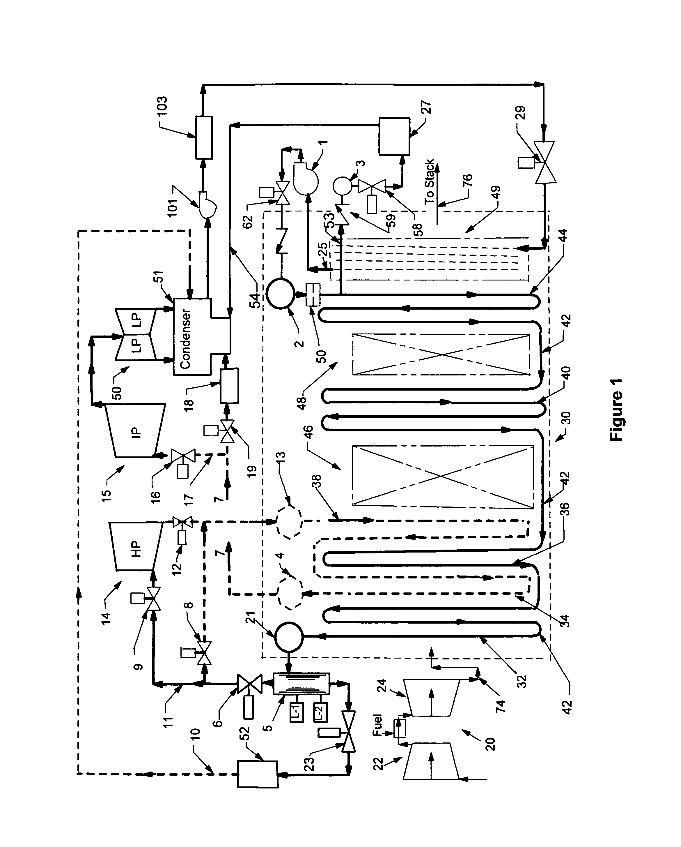
[0026]The current state of the art for HRSGs has several problems that reduce the fatigue life of many high temperature components when required to start fast in cyclical operating duty. The invention can be especially useful with high pressure or supercritical steam combined cycles and reheaters. The invention solves these problems by eliminating components and reducing differential thermal stresses during start. An embodiment of the present invention, FIG. 1 is a schematic of a CC with a three pressure reheat steam HRSG 30. The inventive concept may be incorporated in a single pressure supercritical combined cycle or multi-pressure combined cycle with dual pressure and single pressure cogeneration CCs with and without one or more stages of reheat. It is also applicable to supplementary fired CCs, and steam injected gas turbine HRSGs.

[0027]The embodiment, FIG. 1 includes a gas turbine system 20 comprising a compressor 22, a combustor fuel system and a turbine section 24 that typica...


PUM

PropertyMeasurementUnit
diameteraaaaaaaaaa
temperaturesaaaaaaaaaa
saturation temperatureaaaaaaaaaa

Abstract

A once-through high pressure steam generator and reheater configured to eliminate the majority of components limiting cyclical life of fast start conventional HRSGs. Two remaining problematic components in conventional designs the final superheater and reheater tubes overheat while their headers remain colder in fast starts. In this inventive HRSG the critical components are arranged and started by a method that limits these damaging temperature differentials. At ignition when exhaust gas surges into a wet superheater steam flow starts minutes before conventional systems. This early steam flow cools the tubes while heating the headers, thereby reducing life damaging stresses. Steam temperature is controlled through the start and warms the rest of the plant earlier without attemperators with their problematic thermal stress history. Faster starts than conventional result without damaging fatigue life depletion with this low cost innovation.

Description

BACKGROUND OF THE INVENTION[0001]The present application discloses systems and methods to fast start high pressure heat recovery steam generators (HRSGs) to minimize thermal stress failures experienced by conventional HRSGs. Thousands of Combined Cycle (CC) power plants have been installed and are operating throughout the world. In first thirty years most were installed as base load and designed to be started only a few dozen times a year. Operating experience on many proved that start-stops initiated the greatest damage obliging major repairs, replacement and reduced availability in only a few hundred start cycles for many sites. Increasing the requirement to start faster and more times a year on higher pressure combined cycles necessitates innovative systems and methods focused on solving this proven industry problem. At present CC are often specified to cycle daily and even hourly to load follow and start in 30 minutes (to accommodate solar and wind power variability). To match a...

Claims


Application Information

Patent Timeline
Patent Type & Authority Patents(United States)
IPC IPC(8): F01K13/02F01K7/34F01K19/00F01K7/22F22B1/00
CPCF22B1/00F01K13/02F01K23/101Y02E20/16
Inventor DUFFY, THOMAS, EDWARD
Owner DUFFY THOMAS EDWARD
Why Eureka
Try Eureka