
Metallization system of a semiconductor device comprising extra-tapered transition vias

a transition via and metalization system technology, applied in semiconductor devices, semiconductor/solid-state device details, electrical apparatus, etc., can solve the problems of significant irregularities during the deposition of copper material, non-tolerable signal propagation delays, and difficulty in void-free filling of high aspect ratio vias, etc., to reduce lateral width, reduce lateral dimension, and reduce lateral size

Active Publication Date: 2014-09-16
ADVANCED MICRO DEVICES INC
View PDF10 Cites 4 Cited by
  • Summary
  • Abstract
  • Description
  • Claims
  • Application Information

AI Technical Summary

Benefits of technology

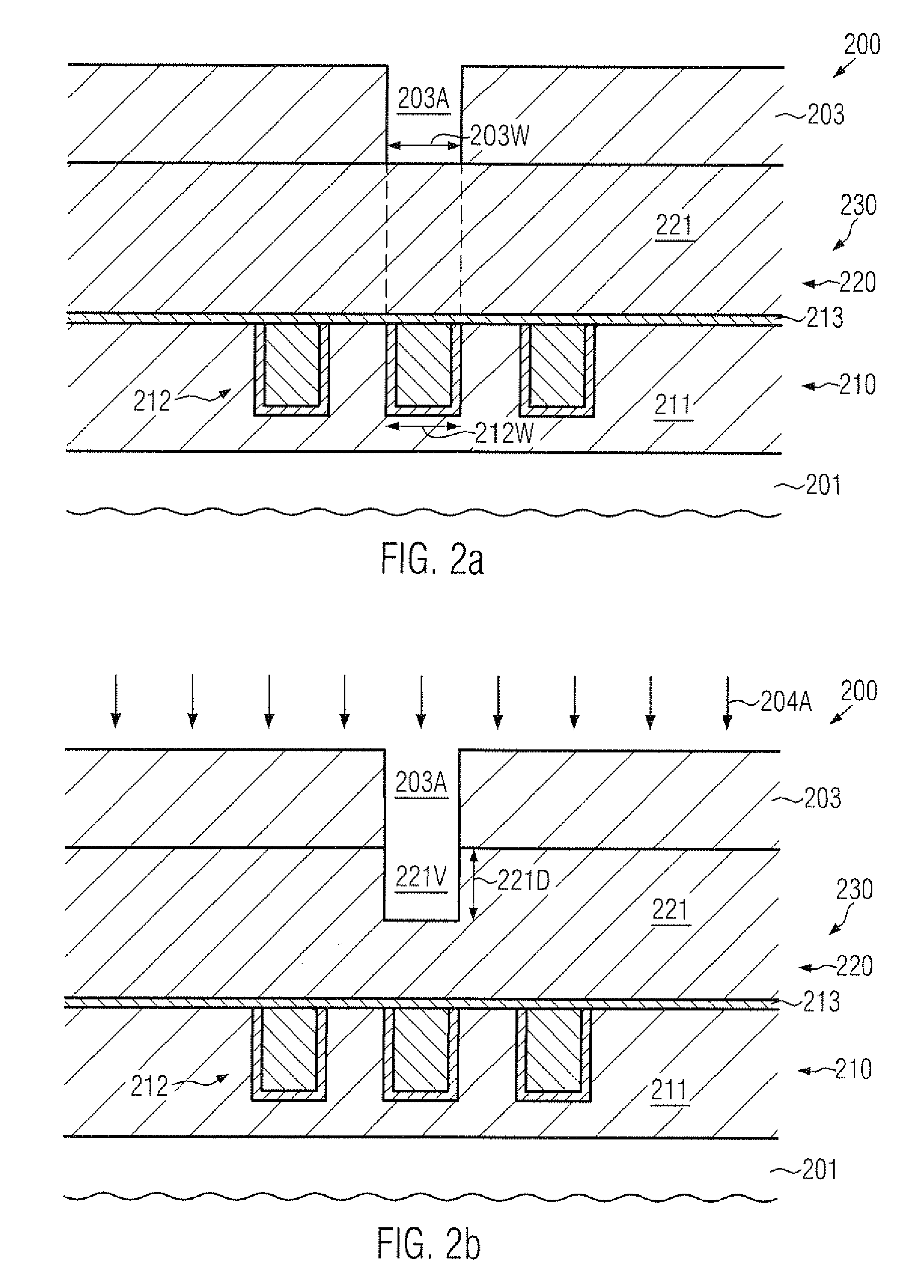
[0015]Generally, the present disclosure provides techniques and semiconductor devices in which the surface topography of a wide trench and a via opening connecting to a metal line of reduced lateral size may be “relaxed” by introducing a pronounced degree of tapering such that a desired reduced lateral width of the via opening may be obtained in the vicinity of the metal line of reduced lateral dimension, while the width of the opening may upwardly increase. Consequently, any constraints imposed on a common deposition process for filling the via opening having the pronounced tapering and the wide trench may be significantly reduced, without requiring dedicated design strategies, which may conventionally result in a reduced packing density. In some illustrative aspects disclosed herein, the pronounced tapering of the via may be accomplished by modifying the etch sequence for forming the via opening in the dielectric material by increasing a corresponding mask opening in a resist mask at least once during the patterning sequence. For instance, the resist material may be “eroded” after performing a first etch step and thereafter a further etch step may be performed on the basis of an increased lateral width of the mask opening. If required, further etch steps may be performed with preceding mask erosion processes in order to obtain a substantially gradual tapering of the resulting via opening. In other illustrative aspects disclosed herein, the etch process for forming the via opening may be performed on the basis of an appropriately designed initial etch mask for forming a first portion of the via opening, while a remaining depth of the via opening may be obtained on the basis of a spacer element, which may also result in a pronounced tapering of the finally obtained via opening.

Problems solved by technology

Although silicon nitride is a dielectric material that effectively prevents the diffusion of copper atoms, selecting silicon nitride as an interlayer dielectric material is less than desirable, since silicon nitride exhibits a moderately high permittivity, thereby increasing the parasitic capacitance of neighboring copper lines, which may result in non-tolerable signal propagation delays.
However, for the dimensions of the metal regions in semiconductor devices, the void-free filling of high aspect ratio vias is an extremely complex and challenging task, wherein the characteristics of the finally obtained copper-based interconnect structure significantly depend on process parameters, materials and geometry of the structure of interest.
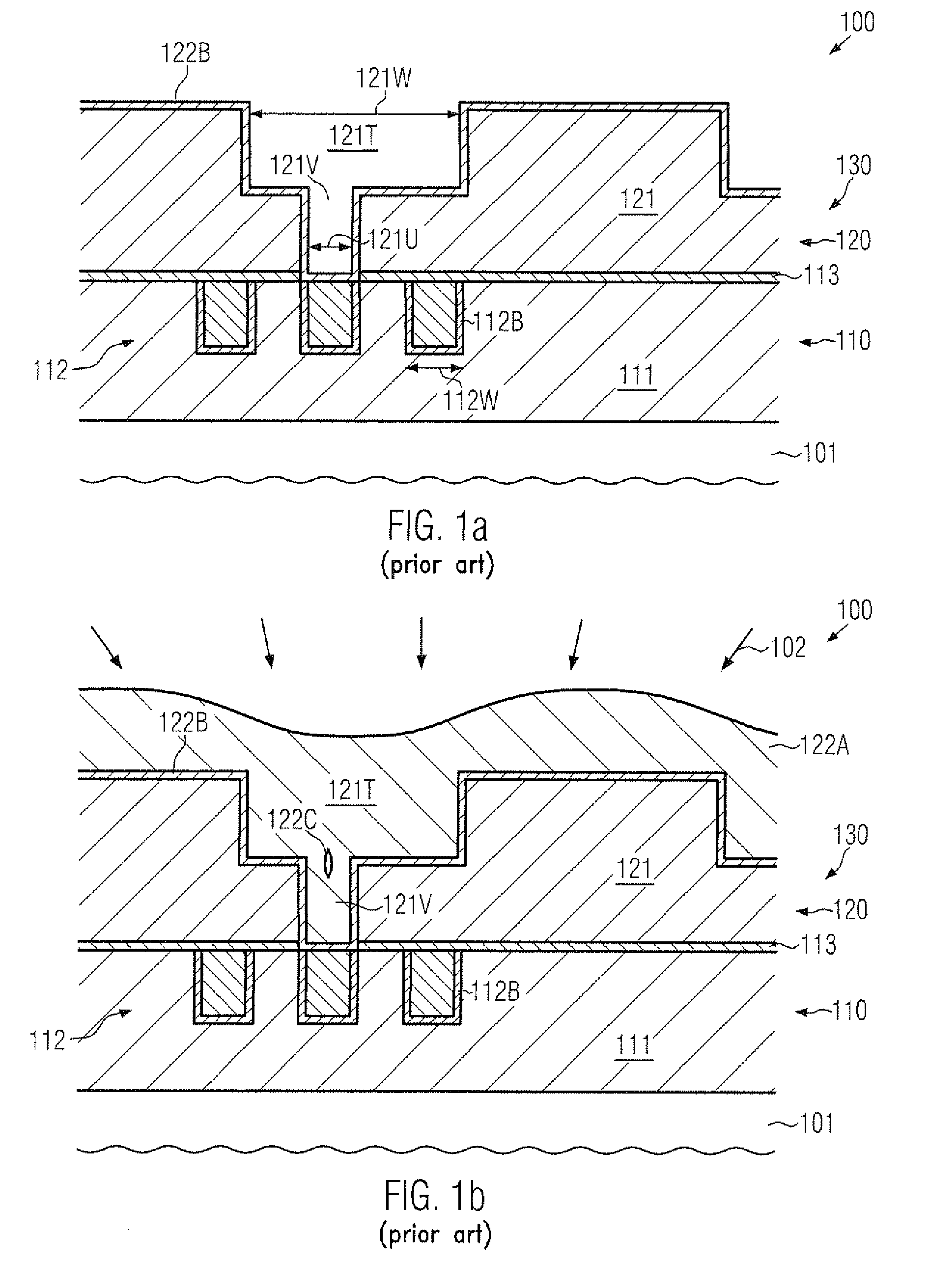
A manufacturing regime according to the dual damascene strategy may, however, result in significant irregularities during the deposition of the copper material due to the significant difference in their lateral width of the corresponding trench and the via, as will be explained in more detail with reference to FIGS. 1a-1b.
However, the sophisticated device topography caused by the per se very complex electrochemical deposition of the copper material may result in deposition irregularities, such as voids 122C, thereby contributing to significant yield losses and reduced reliability of the resulting metallization system 130.
However, due to the significant difference in lateral dimensions of the trench 121T and the via 121V, a premature “closure” of the via opening 121V may result in a corresponding irregularity 122C.
However, a corresponding redesign may generally reduce overall packing density in the metallization system 130.

Method used


Image

  • Metallization system of a semiconductor device comprising extra-tapered transition vias
  • Metallization system of a semiconductor device comprising extra-tapered transition vias
  • Metallization system of a semiconductor device comprising extra-tapered transition vias

Examples


Embodiment Construction

[0024]Various illustrative embodiments of the invention are described below. In the interest of clarity, not all features of an actual implementation are described in this specification. It will of course be appreciated that in the development of any such actual embodiment, numerous implementation-specific decisions must be made to achieve the developers' specific goals, such as compliance with system-related and business-related constraints, which will vary from one implementation to another. Moreover, it will be appreciated that such a development effort might be complex and time-consuming, but would nevertheless be a routine undertaking for those of ordinary skill in the art having the benefit of this disclosure.

[0025]The present subject matter will now be described with reference to the attached figures. Various structures, systems and devices are schematically depicted in the drawings for purposes of explanation only and so as to not obscure the present disclosure with details ...


PUM


Abstract

In a metallization system of a semiconductor device, a transition via may be provided with an increased degree of tapering by modifying a corresponding etch sequence. For example, the resist mask for forming the via opening may be eroded once or several times in order to increase the lateral size of the corresponding mask opening. Due to the pronounced degree of tapering, enhanced deposition conditions may be accomplished during the subsequent electrochemical deposition process for commonly filling the via opening and a wide trench connected thereto.

Description

BACKGROUND OF THE INVENTION[0001]1. Field of the Invention[0002]Generally, the present disclosure relates to microstructures, such as advanced integrated circuits, and, more particularly, to conductive structures, such as copper-based metallization layers, comprising wide metal lines connected to closely spaced narrow metal lines by transition vias.[0003]2. Description of the Related Art[0004]In the fabrication of modern microstructures, such as integrated circuits, there is a continuous drive to steadily reduce the feature sizes of microstructure elements, thereby enhancing the functionality of these structures. For instance, in modern integrated circuits, minimum feature sizes, such as the channel length of field effect transistors, have reached the deep sub-micron range, thereby increasing performance of these circuits in terms of speed and / or power consumption and / or diversity of functions. As the size of individual circuit elements is reduced with every new circuit generation, ...

Claims


Application Information

Patent Timeline
Patent Type & Authority Patents(United States)
IPC IPC(8): H01L21/4763H01L21/768
CPCH01L21/76807H01L21/76804H01L21/76813H01L21/768
Inventor FEUSTEL, FRANKWERNER, THOMASFROHBERG, KAI
Owner ADVANCED MICRO DEVICES INC
Learn More