Solar hot water and recovery system

a recovery system and solar energy technology, applied in indirect heat exchangers, lighting and heating apparatuses, heating types, etc., can solve the problems of water being pumped relatively, the performance and cost effectiveness of a hru for its intended purpose have declined, and the amount of waste heat available as an input to the hru has decreased accordingly. , to achieve the effect of essentially free water heating, reducing consumption and improving the performance of the air conditioning or heat pump system

Active Publication Date: 2014-09-30
GRABOSKI TIMOTHY MICHAEL
View PDF12 Cites 5 Cited by
  • Summary
  • Abstract
  • Description
  • Claims
  • Application Information

AI Technical Summary

Benefits of technology

[0006]When the air conditioning or heat pump system is not running an independent pump system located within the HRU allows for continued solar water heating. The to-be-heated water stream circulates through the second heat exchanger of the heat recovery unit where cross-heat exchange occurs between it and the heat transfer medium of the solar loop, reducing consumption and providing essentially free water heating. When the air conditioning or heat pump system returns to normal operation, extra heat is available from the cross-heat exchange taking place within the first heat exchanger of the HRU and between the solar loop and the refrigerant loop. This also has the benefit of improving the performance of the air conditioning or heat pump system.
[0007]The solar technology reduces the electricity consumption of the standard system. Because an extra heat exchanger is involved as a second heating mechanism, the entire system can achieve a higher desired water temperature in a shorter period of time when compared to other systems, including conventional solar heating and HRU installations. This feature further reduces the amount of electricity consumed.
[0008]Compared to conventional HRU installations, a solar heat recovery system made according to this invention is at least double the efficiency with respect to the amount of heat transferred to the water source. Objects of this invention include but are not limited to the following: (1) enhance the efficiency and effectiveness of a conventional HRU by using solar energy to superheat a refrigerant and use all excess heat for heating the water; (2) heat a contained water source without having to pump portions of that water source to and from a solar panel; (3). continue to solar heat the water source without the assistance of the mechanical equipment (heating or cooling); and (4) enhance the efficiency and effectiveness of heating / cooling units, including those with high seasonal energy efficiency ratings (SEER) (e.g., above about 13 SEER, including those above 20 SEER).

Problems solved by technology

However, as the energy efficiency of air conditioning and heat pump systems have improved over time with better and newer designs, the amount of waste heat available as an input to the HRU has decreased accordingly.
Therefore, the performance and cost effectiveness of a HRU for its intended purpose have declined.
However, this direct heating method requires the water to be pumped relatively long distances.
Additionally, the method is costly because of the need for pumps and multiple collectors or panels to accomplish the heat transfer.

Method used


Image

  • Solar hot water and recovery system
  • Solar hot water and recovery system
  • Solar hot water and recovery system

Examples


Embodiment Construction

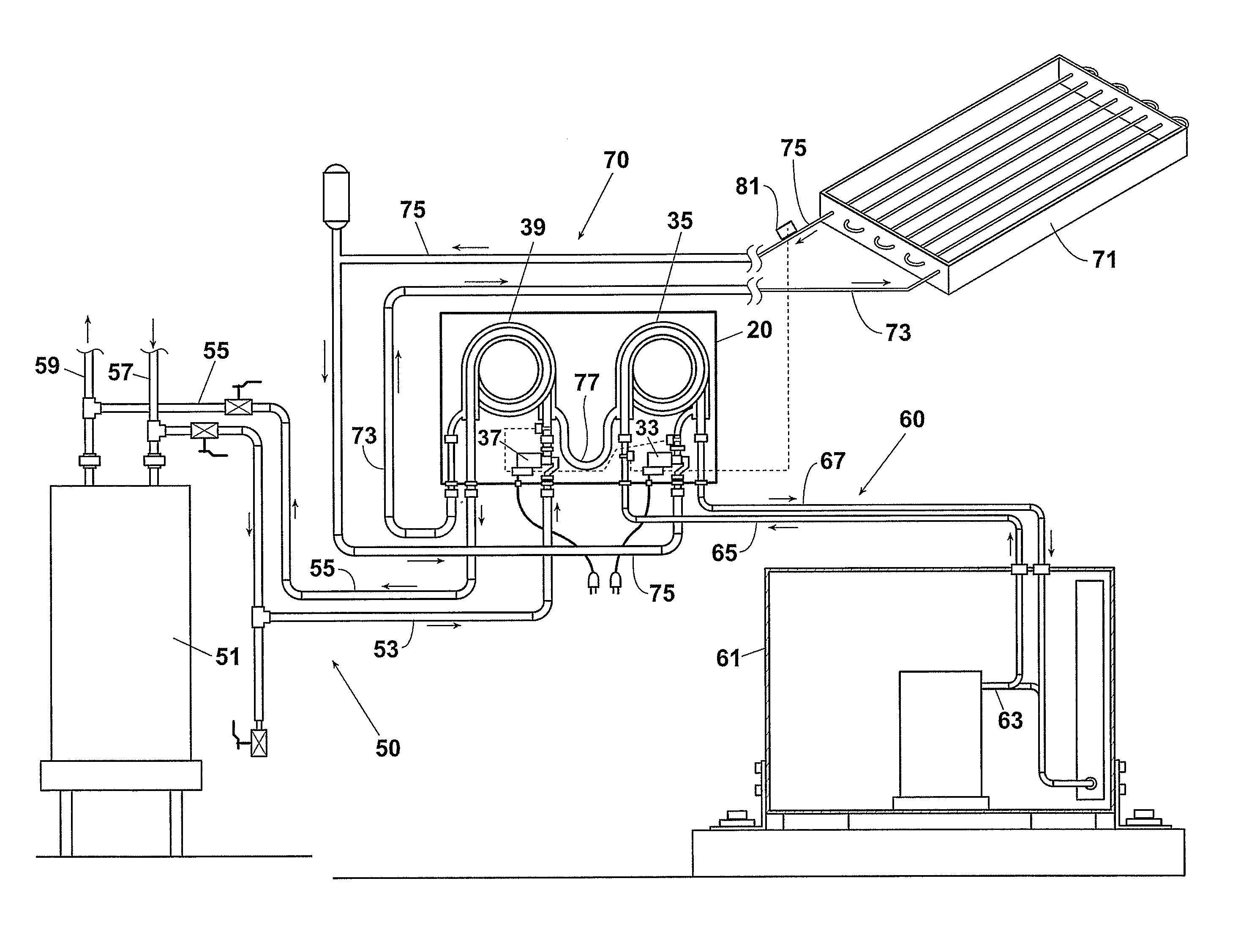
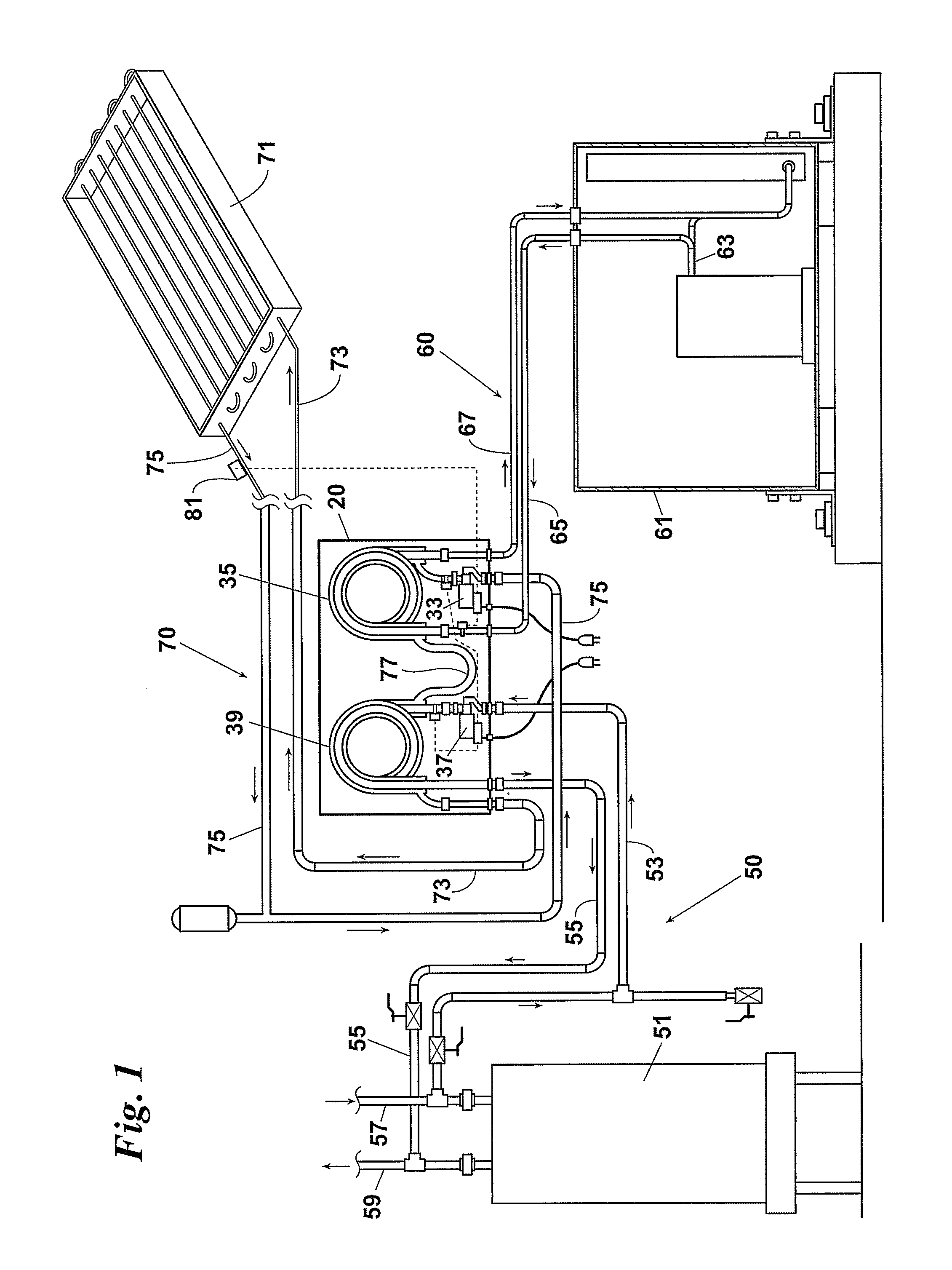
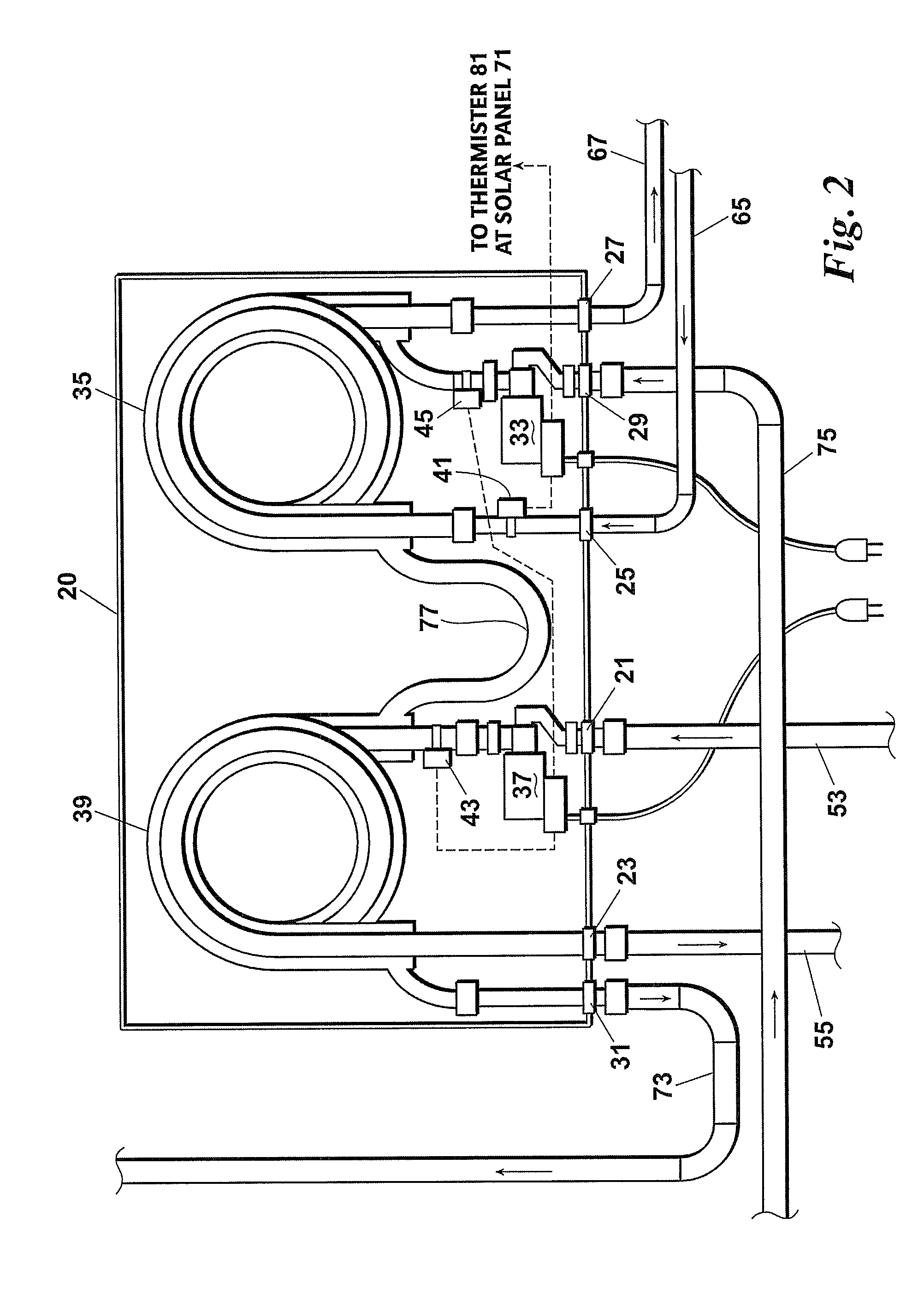
[0012]Referring first to FIG. 1, a solar hot water and recovery system 10 includes a water loop 50, a refrigerant loop 60 and a solar loop 70. Cross-heat exchange occurs in a first heat exchanger 35 between the heat transfer mediums 65, 75 of the refrigerant loop 60 and the solar loop 70 to produce a super-heated fluid stream 67. Cross-heat exchange also takes place in a second heat exchanger 39 between the now-lower temperature heat transfer medium 77 of the solar loop 70 and the water loop 50 to produce a heated water stream 55. More specifically, the system 10 includes the steps of:[0013]routing to a first heat exchanger 35 a first heated fluid stream 65 exiting the hot gas side 63 of a cooling unit 61 and a second heated fluid stream 75 exiting a solar panel 71;[0014]transferring heat between the first heated fluid stream 65 and the second heated fluid stream 75 so as to further heat the first heated fluid stream 75 and produce a first cooled fluid stream 77 and a super-heated f...


PUM


Abstract

A solar hot water and recovery system includes a water loop, a refrigerant loop and a solar loop. Cross-heat exchange occurs in a first heat exchanger between the heat transfer mediums of the refrigerant loop and the solar loop to produce a super-heated fluid stream which is returned to the air conditioning or heat pump unit. Cross-heat exchange also takes place in a second heat exchanger between the now-lower temperature heat transfer medium of the solar loop and the water loop to produce a heated water stream. The main objective of the system is to superheat refrigerant and use all excess heat for heating the water. The heat exchangers are preferably housed in the same heat recovery unit and arranged so that the refrigerant heat exchange area is before the water heat exchange area, thereby maximizing solar potential.

Description

FIELD OF INVENTION[0001]This invention relates generally to systems, apparatuses, and methods for heating water. More particularly, this invention relates to systems, apparatuses, and methods for using solar energy to heat, or provide complementary heating means for, a contained water source.BACKGROUND OF THE INVENTION[0002]A heat recovery unit (“HRU”) is a device well known in the art for capturing waste heat discharged from the refrigerant cycle in an air conditioning or heat pump system. The HRU, which is installed in the refrigerant hot gas line between the compressor and the condenser (on an air conditioner) or between the condenser and reversing valve (on a heat pump system), transfers the captured heat into a hot water tank. To accomplish this transfer, the water side of the HRU is connected in a circulation loop with the hot water tank, with the cold water supply line inlet water stream. By heating a portion of the cold water supply prior to it entering the tank, the HRU red...

Claims


Application Information

Patent Timeline
Patent Type & Authority Patents(United States)
IPC IPC(8): F25B27/00F24J2/00F24J2/30F24D11/00F24D11/02F24S10/30F28D7/02
CPCY02B10/70Y02B10/20F28D7/022F24D11/003Y02B30/52F24D11/0235F24D2200/31F24D11/0221F24D2200/12F24D2200/14Y02B10/24Y02B30/126Y02A30/272
Inventor GRABOSKI, TIMOTHY, MICHAEL
Owner GRABOSKI TIMOTHY MICHAEL
Why Eureka
Try Eureka