
Method of manufacturing semiconductor device

a semiconductor and manufacturing method technology, applied in the direction of semiconductor devices, electrical devices, transistors, etc., can solve the problems of inapplicability of conventional polysilicon/sion systems, inability to cope with relatively high field strength, and inability to effectively control metal gate work functions, so as to improve resistance regulating layer filling space, simplify metal gate structure, and improve the effect of metal gate work function

Active Publication Date: 2014-10-07
INST OF MICROELECTRONICS CHINESE ACAD OF SCI
View PDF9 Cites 2 Cited by
  • Summary
  • Abstract
  • Description
  • Claims
  • Application Information

AI Technical Summary

Benefits of technology

[0008]As stated above, the present invention aims to overcome the above problem, to thereby control the metal gate work function effectively while decreasing the gate resistance efficiently.
[0023]In accordance with the semiconductor device and the method of manufacturing the same in the present invention, a PMOS work function regulating layer is deposited after a NMOS work function regulating layer is selectively deposited, thus the PMOS metal gate structure is simplified, the metal gate work function is effectively controlled while the filling space of the resistance regulating layer is increased, thereby the gate resistance is reduced effectively.

Problems solved by technology

However, the ultra-thin (e.g., 10 nm) conventional oxide layer or oxynitride layer may result in severe gate current leakage since the (relative) dielectric constant is not high (e.g., about 3.9) and the insulating capability can hardly endure the relatively high field strength in such an ultra-small device.
Hence, a conventional polysilicon / SiON system is no longer applicable.
However, the interfacial charges and polarization charges of high-K materials will cause difficulty in regulating the threshold of a device, and the combination of polysilicon and high-K materials will produce a Fermi-level pinning effect, thus such combination of polysilicon and high-K materials can not be used for regulating the threshold of a MOSFET, accordingly, the gate electrode shall employ different metal materials to regulate the threshold of a device, that is, using a metal gate (MG) / HK structure.
The regulation method using a single metal gate material may be adopted, but the range of regulation is limited.
However, the device threshold is hard to be effectively controlled by such a fine regulation within a small range.
Thus, in the device structure of the PMOS region, the metal gate structure is extremely complex (comprising three blocking layers), in a condition where the feature size-the gate length is continuously reduced, particularly when the gate length is below 22 nm, since the structure of the multi-layer blocking layer causes a decrease in the space of the resistance regulating layer of the PMOS region which can be filled, problems will occur where the gate resistance is difficult to be effectively reduced due to small size of the resistance regulating layer and the resistivity is increased due to holes formed by insufficient filling.

Method used


Image

  • Method of manufacturing semiconductor device
  • Method of manufacturing semiconductor device
  • Method of manufacturing semiconductor device

Examples


Embodiment Construction

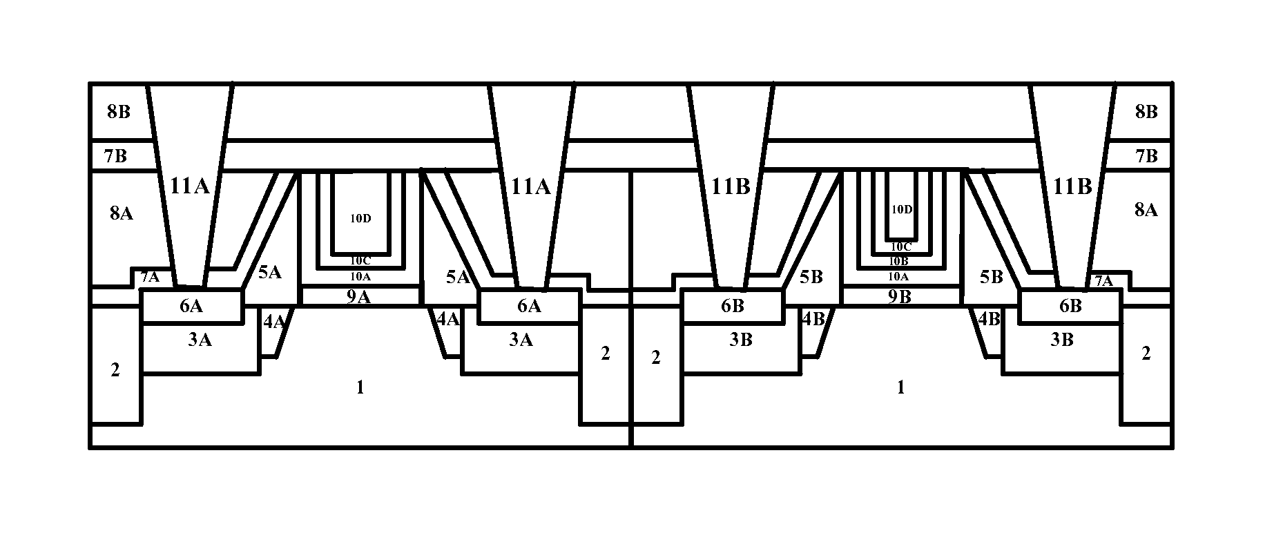
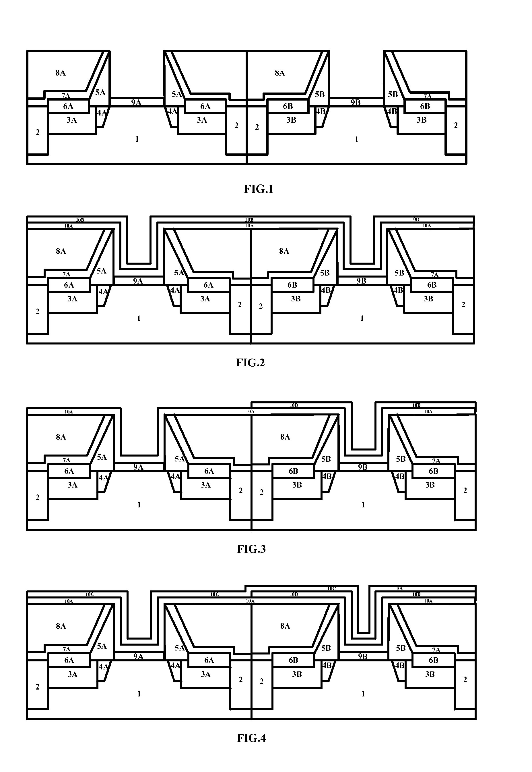
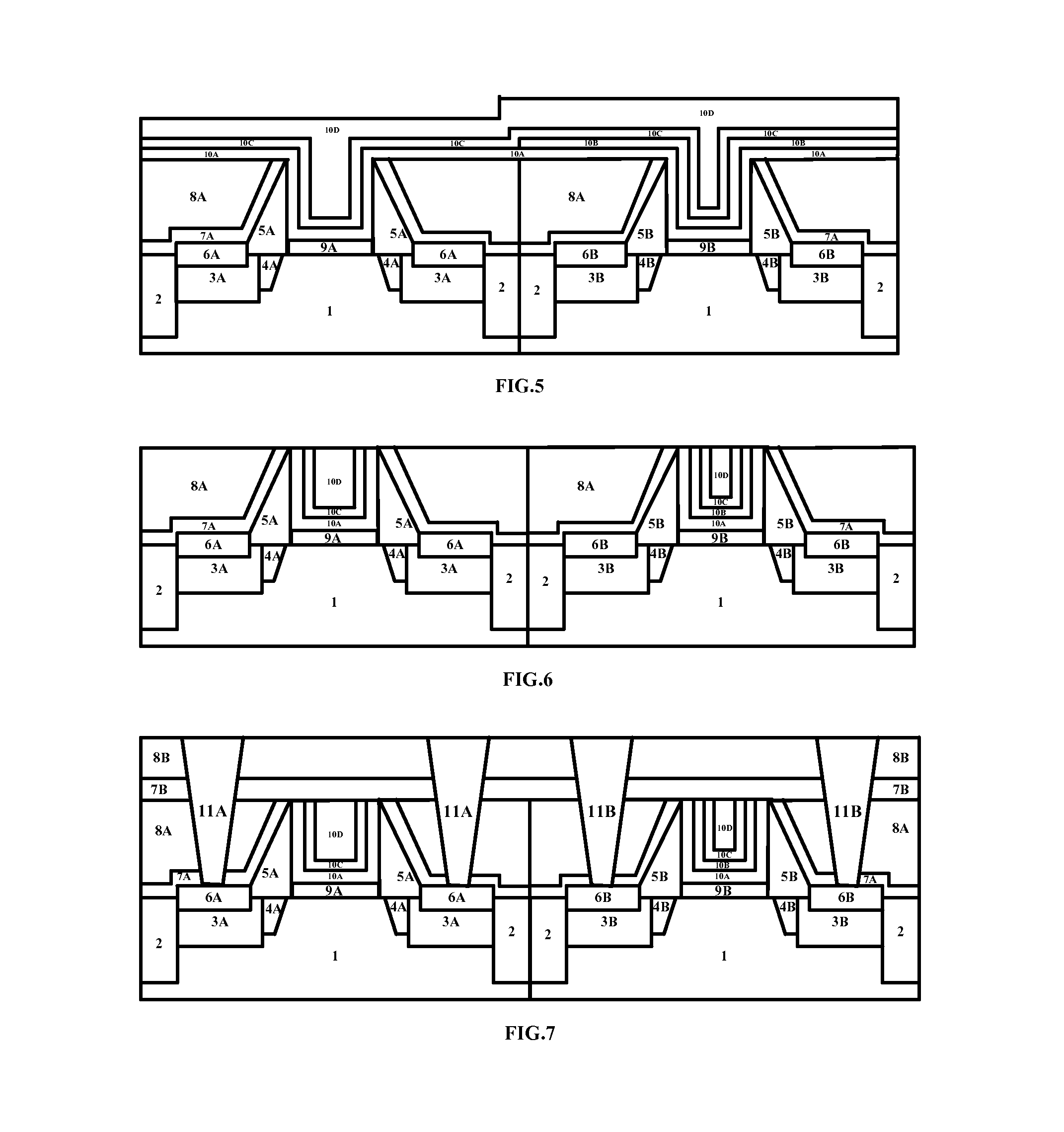
[0026]The features of the technical solutions of the present invention and the technical effects thereof are explained in detail in combination with the illustrative embodiments with reference to the drawings below, and disclosed herein a CMOS capable of controlling a metal gate work function effectively while reducing the gate resistance efficiently and a method of manufacturing the same. It shall be noted that like reference signs indicate like structures, and the terms like “first”, “second”, “on” and “below” etc. used in the present application may be used to modify various device structures or manufacturing processes. Unless specific explanations, such modifications do not imply the spatial, sequential or hierarchical relationships of the device structures or manufacturing processes.

[0027]The steps of the method for manufacturing a CMOS in accordance with the present invention will be described in detail with reference to the diagrammatic cross-sections in FIGS. 1-7, wherein th...


PUM


Abstract

The present invention discloses a method for manufacturing a semiconductor device comprising the steps of: forming a plurality of source and drain regions in a substrate; forming a plurality of gate spacer structures and an interlayer dielectric layer around the gate spacer structures on the substrate, wherein the gate spacer structures enclose a plurality of first gate trenches and a plurality of second gate trenches; sequentially depositing a first gate insulating layer and a second gate insulating layer, a first blocking layer and a second work function regulating layer in the first and second gate trenches; performing selective etching to remove the second work function regulating layer from the first gate trenches to expose the first blocking layer; depositing a first work function regulating layer on the first blocking layer in the first gate trenches and on the second work function regulating layer in the second gate trenches; and depositing a resistance regulating layer on the first work function regulating layer in the first gate trenches and on the first work function regulating layer in the second gate trench.

Description

CROSS REFERENCE[0001]This application is a National Phase application of, and claims priority to, PCT Application No. PCT / CN2012 / 001153, filed on Aug. 27, 2012, entitled ‘SEMICONDUCTOR DEVICE AND METHOD OF MANUFACTURING THE SAME’, which claimed priority to Chinese Application No. CN 201210258854.0, filed on Jul. 24, 2012. Both the PCT Application and Chinese Application are incorporated herein by reference in their entireties.FIELD OF THE INVENTION[0002]The present invention relates to a semiconductor device and a method of manufacturing the same, more particularly, to a CMOS that is capable of more effectively controlling the work function and decreasing the gate resistance and a method of manufacturing the same.BACKGROUND OF THE INVENTION[0003]Starting from the 45 nm CMOS integrated circuit technology, with continuous reduction in the device feature size, the equivalent oxide thickness (EOT) of a gate insulating dielectric layer in a CMOS device must be reduced synchronously to su...

Claims


Application Information

Patent Timeline
Patent Type & Authority Patents(United States)
IPC IPC(8): H01L21/8238
CPCH01L27/088H01L21/82345H01L21/823842H01L27/092H01L29/4966H01L29/517H01L29/66545H01L29/66666H01L29/7848
Inventor YIN, HUAXIANGYAN, JIANGCHEN, DAPENG
Owner INST OF MICROELECTRONICS CHINESE ACAD OF SCI
Learn More