Solid-state lithium battery

a lithium battery and solid-state technology, applied in the field of solid-state lithium batteries, can solve the problems of limiting the life-time of batteries, fracturing of films, heat transfer loss, etc., and achieve the effect of improving power over conventional materials and low form factor

a lithium battery and solid-state technology, applied in the field of solid-state lithium batteries, can solve the problems of limiting the life-time of batteries, fracturing of films, heat transfer loss, etc., and achieve the effect of improving power over conventional materials and low form factor

US8877388B1Active Publication Date: 2014-11-04NAT TECH & ENG SOLUTIONS OF SANDIA LLC

Image

  • Solid-state lithium battery
  • Solid-state lithium battery
  • Solid-state lithium battery

Examples


Embodiment Construction

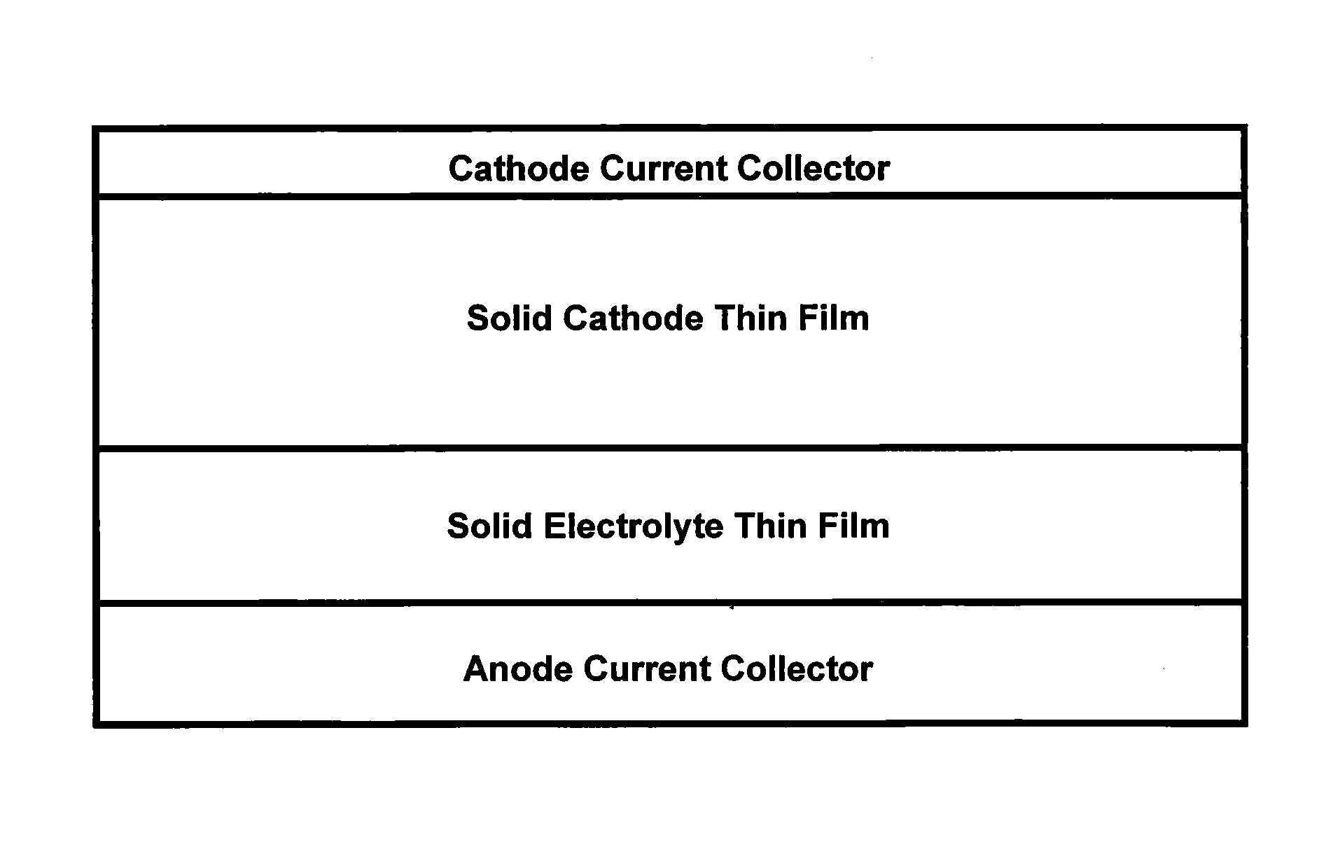
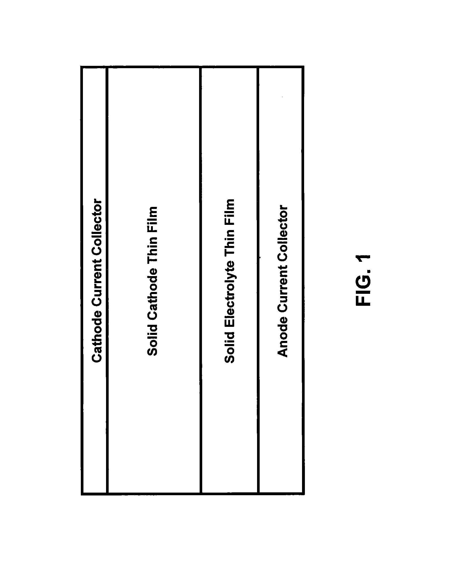
[0027]As shown in FIG. 1, a solid-state lithium microbattery can comprise a thin film of a first nonaqueous material, such as copper or nickel, that functions as an anode current collector, upon which is deposited optionally a thin-film anode (not shown) comprising a nonaqueous material such as lithium or lithium titanate, upon which is a nonaqueous solid electrolyte thin film layer that comprises a lithium-rare earth metal-containing compound. A solid nonaqueous cathode thin film is layered on top of the electrolyte thin film layer, followed by a nonaqueous thin film cathode current collector, such as an aluminum layer. Optionally, a separator membrane (not shown) can be between layers, such as between the nonaqueous electrolyte thin film layer and the solid cathode thin film layer.

[0028]The anode current collector can comprise a thin film of copper or nickel that is in one embodiment approximately 0.2 to approximately 5 microns in thickness or in another embodiment a tape or foil ...


PUM

PropertyMeasurementUnit
crystallization temperatureaaaaaaaaaa
decomposition voltagesaaaaaaaaaa

Abstract

The present invention is directed to a higher power, thin film lithium-ion electrolyte on a metallic substrate, enabling mass-produced solid-state lithium batteries. High-temperature thermodynamic equilibrium processing enables co-firing of oxides and base metals, providing a means to integrate the crystalline, lithium-stable, fast lithium-ion conductor lanthanum lithium tantalate (La1 / 3-xLi3xTaO3) directly with a thin metal foil current collector appropriate for a lithium-free solid-state battery.

Description

CROSS-REFERENCE TO RELATED APPLICATIONS[0001]This application is a continuation-in-part of U.S. application Ser. No. 12 / 690,189, filed Jan. 20, 2010, and claims the benefit of U.S. Provisional Application No. 61 / 521,118, filed Aug. 8, 2011, both of which are incorporated herein by reference.STATEMENT OF GOVERNMENT INTEREST[0002]This invention was made with Government support under contract no. DE-AC04-94AL85000 awarded by the U.S. Department of Energy to Sandia Corporation. The Government has certain rights in the invention.FIELD OF THE INVENTION[0003]The present invention relates to solid-state batteries and, in particular, to a solid-state lithium battery and a method for thin-film lithium-ion electrolyte fabrication for use in such solid-state lithium batteries.BACKGROUND OF THE INVENTION[0004]A battery is an electrochemical device that converts the energy released in a chemical reaction directly into electrical energy. In a battery, the reactants are stored close together within...

Claims


Application Information

Patent Timeline
04 Nov 2014
Publication
US8877388B1
IPC
H01M10/0562; H01M50/403
CPC
H01M10/0562; C01G35/006; C01P2002/72; C01P2004/03; C01P2004/04; C01P2006/40; H01M2/145; H01M6/40
Inventors
IHLEFELD, JON; CLEM, PAUL G.