Debugging control system using inside core event as trigger condition and method of the same

a control system and core event technology, applied in error detection/correction, instruments, digital data processing details, etc., can solve the problems of insufficient comparison mode of trigger events, inability to modify trigger events, and difficulty in finding bugs in practice, so as to achieve significant improvement in the debugging efficiency of integrated circuits and reduce the debugging time of integrated circuits. , the effect of high degree of freedom

Active Publication Date: 2014-11-18
NAT CHENG KUNG UNIV
View PDF4 Cites 0 Cited by
  • Summary
  • Abstract
  • Description
  • Claims
  • Application Information

AI Technical Summary

Benefits of technology

[0007]Therefore it is primary object of the present invention to provide cores designed for debugging and added into an intellectual property (IP) during the design of the integrated circuit. After finishing production of the integrated circuit or being written with programmable logic arrays, these cores form a debugging system that performs debugging process in the IP. A debugging control method is also revealed. Moreover, values in registers of a core under debug can be modified by a graphical interface software module. Thus the core under debug can be resumed to execute its original programs according to current internal states while turning from a paused state to a normal state. Therefore the debugging time of the integrated circuit is significantly reduced.
[0016]Thereby all flip-flops in the core under debug can be used as targets of the trigger events and signals of the scan chains of the IP can be selected freely and used as trigger signals to set trigger events. The logical relations, the sequencing order and the number of occurrences of each trigger event can be combined freely and used as a trigger condition. A high degree of freedom is provided and the debugging efficiency of the integrated circuit is significantly increased. Moreover, values in the register of the core under debug are changed by the graphical interface software module so that the core under debug is adjusted to the state the user expected while the core under debug returning from the paused state to the normal state. Then the paused state of the core under debug is released and the core under debug is resumed to execute original programs according to the current internal state. And there is no need to start verification from the beginning repeatedly. Thus not only the debugging time for the integrated circuit is reduced, observability and controllability of the core are also increased so as to improve debugging performance of the core under debug. Therefore bugs in the core are quickly found out by the present invention and the difficulty in debugging of the integrated circuit is reduced.

Problems solved by technology

Although the occurrences of the trigger events can be detected correctly, the trigger events are unable to be modified due to the fixed signals and the comparator.
It's quite hard to find out bugs in practice.
Moreover, the fixed comparator used has limits on the trigger events and this leads to insufficient comparison mode for the trigger event.
However, not all signals in a core under debug (such as intellectual property (IP)) have the capability to reorganize the trigger events.
Thus the signals are difficult to be modified and used as trigger events and most of tracing and debugging is unable to record all signals inside the core.
Thus the data resolution obtained is not sufficient for users to find out where errors occurred.
After finishing production of the integrated circuit, the debug and trace method available now lacks observability and controllability of the signals in the IP.
Thus circuit errors can only be observed through output / input ports of the integrated circuit during verification of the IP and there is no way to observe internal states of the core directly.
Therefore it's difficult to find out and remove bugs of the integrated circuit.
However, the system and the method mentioned above has following disadvantages: (a) User are unable to select signals of the scan chains of the IP freely and use them as trigger signals and set trigger events.
Thus they need to spend more time to find out bugs in the IP.

Method used


Image

  • Debugging control system using inside core event as trigger condition and method of the same
  • Debugging control system using inside core event as trigger condition and method of the same
  • Debugging control system using inside core event as trigger condition and method of the same

Examples


Embodiment Construction

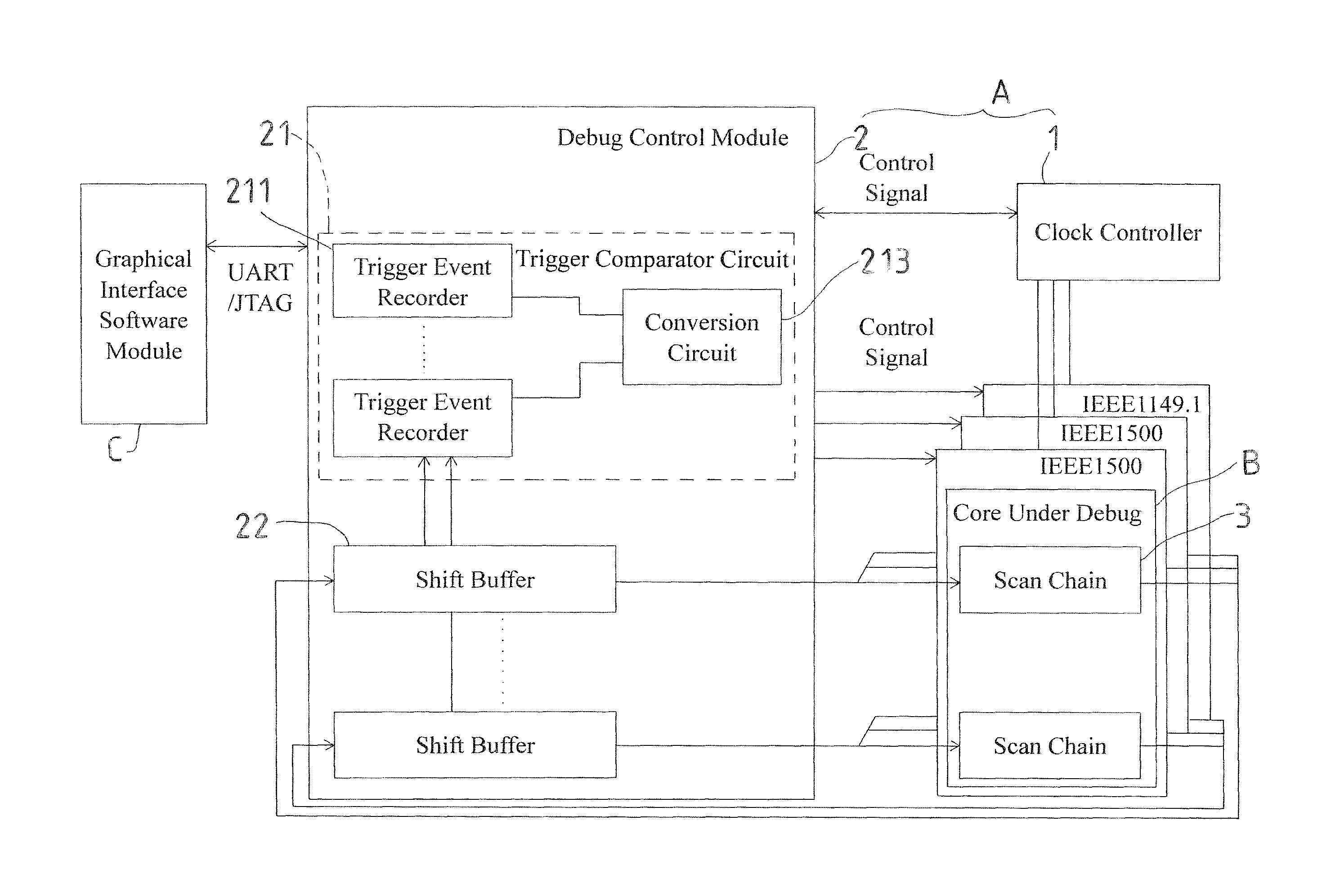
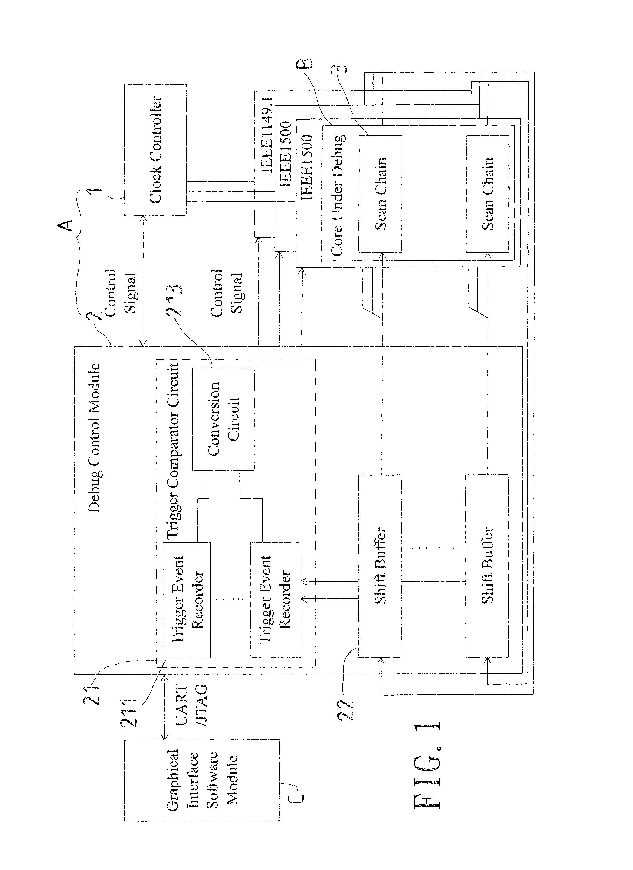
[0027]Refer to FIG. 1, an embodiment of a debugging control system (A) of the present invention is applied to a core under debug (B) and a graphical interface software module (C) is for users to input a block diagram showing electrical connections being set. The debugging control system (A) that uses inside-core events as trigger conditions according to the present invention includes a clock controller 1 and a debug control module 2.

[0028]The clock controller 1 outputs pause clock and recovery clock to the core under debug (B) within a specified search range of clock cycle for control of the core under debug (B) in a debug mode and a normal mode respectively. The debug control module 2 consists of a trigger comparator circuit 21 and at least one shift buffer 22. In the debug mode, data in the core under debug (B) is transmitted to the shift buffer 22 via a pathway of at least one scan chain (3) and is temporarily saved in the shift buffer 22. Then the data is used by the trigger com...


PUM


Abstract

A debugging control system using inside-core events as trigger conditions and a method of the same are revealed. The method includes following steps. First set up at least one trigger condition and a search range of the clock cycle according to internal states of a core under debug. Pause clock and recover clock of each clock cycle within the search range. Retrieve data of scan chains of the core under debug by a shift buffer during the clock pausing. Next combine data of the scan chains by a trigger comparator circuit to form trigger signals and check whether the trigger signals satisfy the trigger condition. If the trigger condition is satisfied or the trigger signal is over the search range, the clock is paused continuingly and internal states of the scan chains of the core under debug are output otherwise the core under debug is recovered.

Description

BACKGROUND OF THE INVENTION[0001]1. Fields of the invention[0002]The present invention relates to a debugging control system that uses inside-core events as trigger conditions and a method of the same, especially to a debugging control system that uses inside-core events as trigger conditions and a method of the same that adds cores designed for debugging into intellectual property (IP) during the design of integrated circuit for debugging of the IP after finishing production of the integrated circuit or the cores being written with programmable logic arrays. Moreover, values in registers of the core under debug are changed by a graphical interface software module so that the core under debug can be resumed to execute original programs according to the current internal state when the core under debug returns from a paused state to a normal state. The debugging time for the integrated circuit is dramatically reduced.[0003]2. Descriptions of Related Art[0004]Generally, a conventional ...

Claims


Application Information

Patent Timeline
Patent Type & Authority Patents(United States)
IPC IPC(8): G01R31/3177G06F11/00G06F1/00G01R31/28
CPCG01R31/31705G01R31/3177
Inventor LEE, KUEN-JONGJHOU, JIA-WEI
Owner NAT CHENG KUNG UNIV
Why Eureka
Try Eureka