

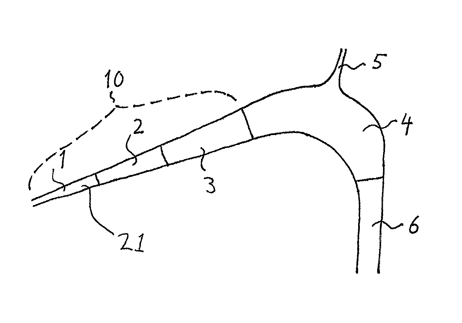
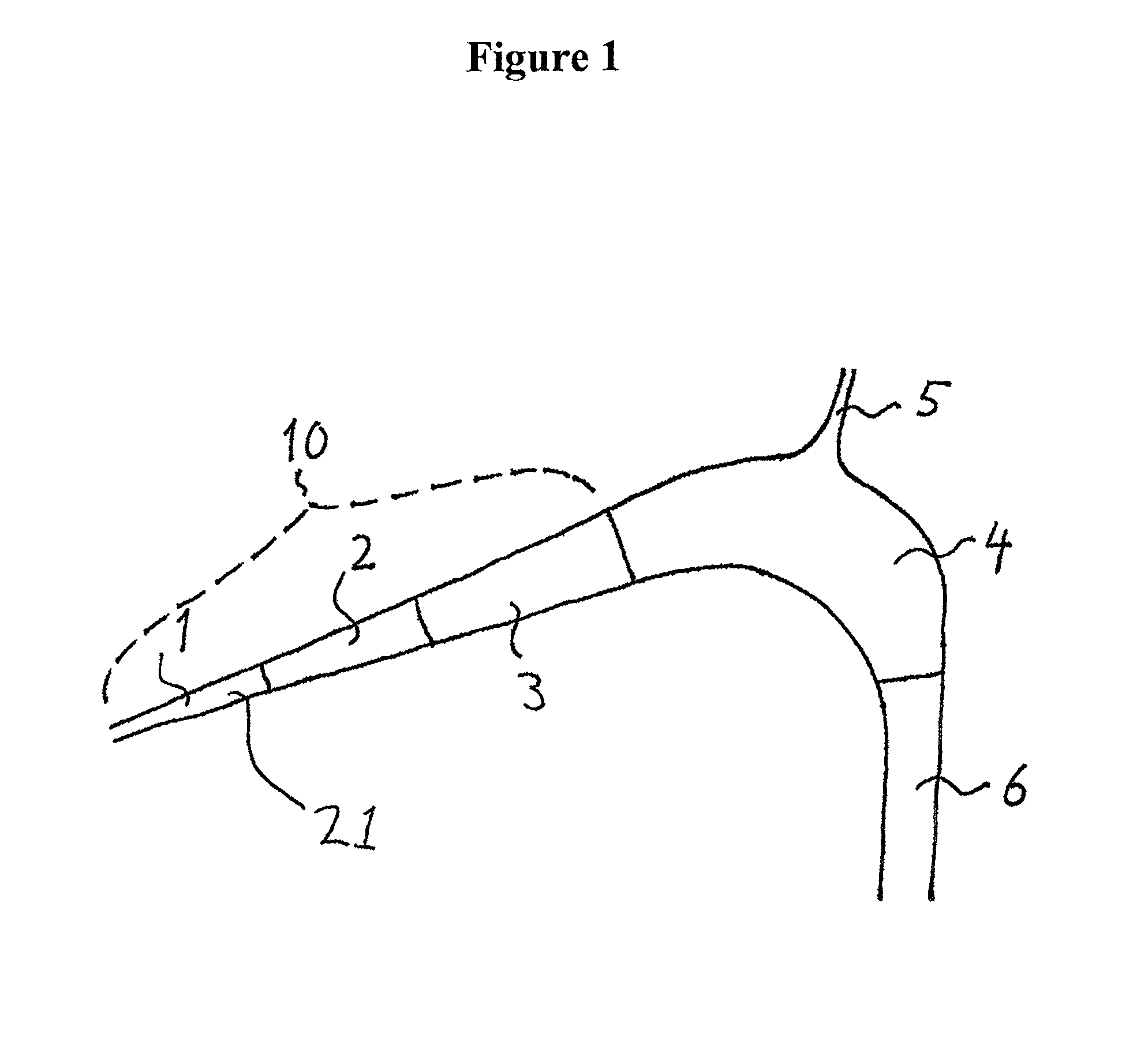
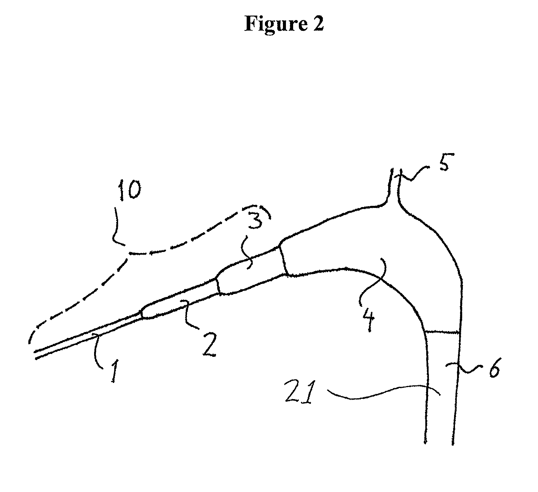
Bubble reducer for eliminating gas bubbles from a flow
a gas bubble and reducer technology, applied in the field of bubble reducers, can solve the problems of affecting the treatment effect of patients, and affecting the effect of the patient's renal replacement therapy, so as to achieve the effect of improving the cross-sectional area, reducing the risk of death, and convenient manufacturing
- Summary
- Abstract
- Description
- Claims
- Application Information
AI Technical Summary
Benefits of technology
Problems solved by technology
Method used
Image

Examples
examples
Materials and Methods
[0063]A prototype developed based on the present invention was compared to products currently on market, device A and device B. A standardized bubble generator was employed to generate bubbles of varying size, including microbubbles, in a solution commonly used as a blood substitute within the dialysis field. The utilized solution contains dextran and albumin and has the same viscosity as normal blood.
[0064]The solution was re-circulated from the solution-containing vessel, wherein bubbles had been produced by the bubble generator, into a dialysis tubing system of either device A or device B, or the prototype of the present invention, alternately. Bubbles present downstream of the venous chamber were detected and measured using a Hatteland Instrument (Royken, Norway), as previously described elsewhere. The measurements were performed alternately between the systems for each blood flow measured in order to reduce the risk of uneven bubble distribution and potenti...
PUM
| Property | Measurement | Unit |
|---|---|---|
| length | aaaaa | aaaaa |
| angle | aaaaa | aaaaa |
| angle | aaaaa | aaaaa |
Abstract
Description
Claims
Application Information