
Rechargeable magnesium ion cell components and assembly

a technology of magnesium ion cells and components, applied in the direction of cell components, non-aqueous electrolyte cells, electrochemical generators, etc., can solve the problem that the electrical conductivity does not necessarily provide in itself, and achieve the effects of improving anodic stability, improving chemical inertness, and cost-effectiveness

Inactive Publication Date: 2015-02-10
PELLION TECH
View PDF21 Cites 2 Cited by
  • Summary
  • Abstract
  • Description
  • Claims
  • Application Information

AI Technical Summary

Benefits of technology

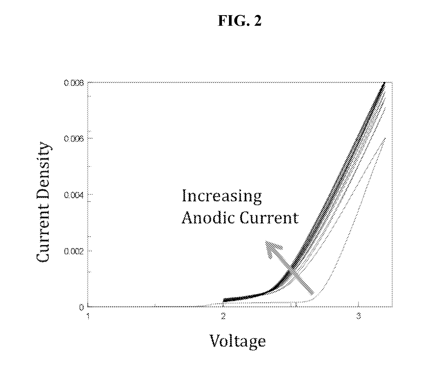
[0005]Barrier materials, also referred to as overlayer materials, which improve the chemical inertness for current collectors made of metals such as Al, Cu, and stainless steel for magnesium batteries comprised of material are disclosed herein. As used herein, a barrier material refers to a material that is more chemically and electrochemically inert than is the material from which the current collector is constructed with regard to reaction with other cell components, such as an electrolyte for a magnesium battery. The purpose of the barrier material is to eliminate insofar as possible the likelihood of a chemical interaction between the metal being covered and a substance in the electrolyte that is used in the battery, while maintaining electrical connectivity between the current collector, composite electrode, and the electrolyte. In particular, it is recognized that when a first metal has a second metal deposited thereon to form such a barrier layer, the exact composition of the region near the interface between the first metal and the second metal may vary in composition depending on how the first metal and the overlayer of the second metal are assembled and their respective microstructures. The region near the interface may vary in composition over time, depending on such things as the mechanical, electrical and thermal history that may be applied to the interface region, because interdiffusion and alloying behavior between metals is known to occur in some instances. As used herein, it is to be understood that a usage such as “a first metal having a second metal as a barrier layer” is intended to denote the starting compositions of the first and the second metal, or equally, the compositions of the first metal and the second metal at a distance from the interface region, and should not necessarily be taken to mean the exact composition of the composite at the interface. Non-limiting examples of barrier materials include W, WC, Ta, and TiN. It is believed that other metals from Group 4, Group 5 and Group 6 of the periodic table, as well as their metal carbides and metal nitrides, will also perform well as barrier materials or overlayer materials. In some embodiments, the current collector in whole comprises the barrier material. In other embodiments, the current collector in part comprises the barrier material. In some embodiments, the current collector includes form factors, including but not limited to sheet, film, foil, tubes, microfoil, coating or laminate upon metal foil, plate, and rod. The resulting current collector is inert towards Mg electrolytes and significantly improves the anodic stability with respect of the reactivity to the magnesium electrolyte. The barrier materials for current collector disclosed herein enables cost-effective fabrication of magnesium batteries.Barrier Materials Selection
[0006]In the selection of a material as a barrier material a goal is the achievement of an electrically conducting composite electrode current collector that is resistant to chemical reaction with the components of an electrolyte that is used in a battery. In the ideal case, the electrically conducting composite electrode current collector chemically inert as regards the electrolyte and its components, but it is acceptable if the electrically conducting composite electrode current collector is sufficiently corrosion resistant that degradation over a useful operational lifetime of a battery is so low that the battery performs acceptably. The composite electrode current collector includes a core material which is overcoated with an overlayer of a barrier material. There are several approaches that can be used. The first approach is to choose a highly-conductive coating material having sufficient electrical conductivity to serve as a current collector, which would allow the choice of a range of substrates (even including insulators) as the core. In such an embodiment, the core is relied upon as a mechanical support or shape-defining structure of the electrically conducting composite electrode current collector but does not necessarily provide electrical conductivity in itself. A second approach is to choose a very conductive material as the core, which would allow the choice of a range of coatings (again even including insulators in a form thin enough to allow electrical current to pass through the thickness of the coating, for example by quantum mechanical tunneling). In such an embodiment. the core is relied upon both as a mechanical support or shape-defining structure of the electrically conducting composite electrode current collector and as a structure that can provide electrical conductivity.
[0008]The substrate or core, as one result of this invention, can be a conventional low-resistance current collector material such as Al and Cu, which is protected by the barrier layer when used in a corrosive electrolyte. In an alternative embodiment, a low-resistance barrier material would allow the use of a very wide range of substrate or core materials, including conducting core materials and insulating core materials that provide a mechanical support and a shape for a conductive barrier layer. Insulating substrate materials including by way of example plastic foil can be highly beneficial to both the cell manufacturing and materials cost. Thus this invention allows considerable freedom for selection of materials of construction that can provide an improved substrate / barrier / cathode combination to achieve reduced battery cost and improved performance.
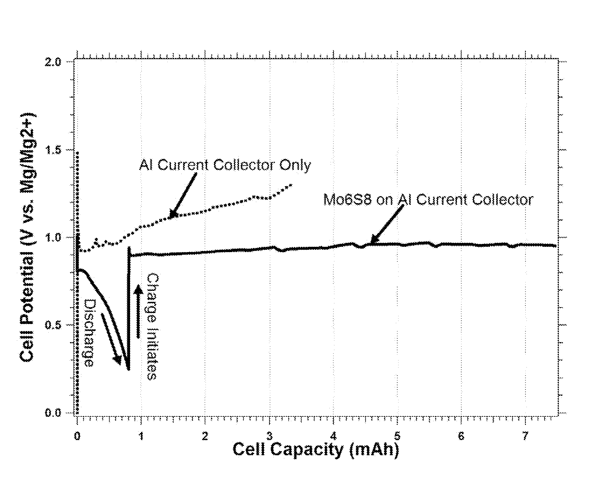
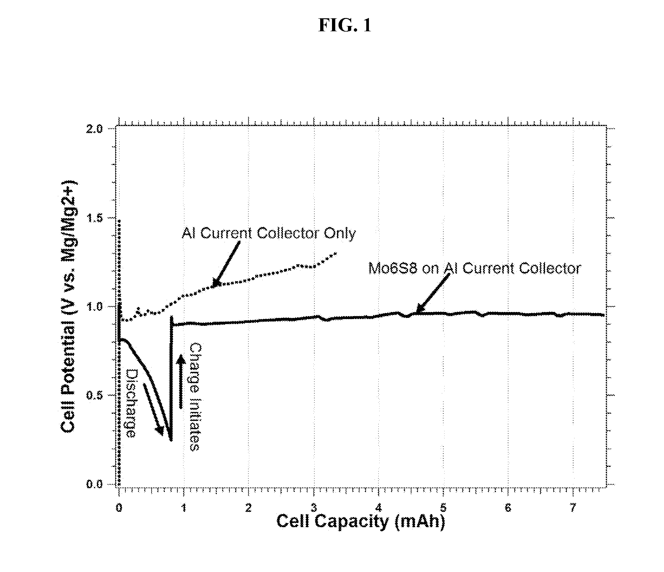
[0009]This invention enables significant increases in the useful voltage of a Magnesium (Mg) ion cell by employing current collectors with barrier materials to support the electrode material thus inhibiting corrosion reactions common to many metals and alloys immersed in Mg ion electrolyte solutions that limit the voltage and capacity of the cell.
[0011]Current collectors for magnesium batteries comprised of carbonaceous material are disclosed herein. As used herein, carbonaceous material refers to materials containing carbon in whole and in part, which provide an electronically conducting support that is chemically and electrochemically inert from reaction with other cell components, for a Magnesium battery active materials. Non-limiting examples of carbonaceous materials include graphite, carbon fiber, glassy carbon, amorphous carbon, and pyrolitic carbon. In some embodiments, the current collector in whole comprises carbon. In other embodiments, the current collector in part comprises carbon. Non-limiting examples of current collector comprising carbon in part includes metal coated with carbon such as GrafTech Grafoil Metal Reinforced Laminate Grades TG-251, GHJ, GHE, GHR, GHH, and Showa Denko SDX. In some embodiments, the carbon-comprising current collector includes form factors, including but not limited to sheet, film, foil, tubes, microfoil, coating or laminate upon metal foil, plate, and rod. The carbon-containing current collector is inert towards Mg electrolytes and results in anodic stability comparable to magnesium battery using noble metals such as Pt as the current collector. The carbon-containing current collector disclosed herein enables cost-effective fabrication of magnesium batteries.
[0012]This invention enables significant increases in the useful voltage of a Magnesium (Mg) ion cell by employing carbonaceous current collectors to support the electrode material thus inhibiting corrosion reactions common to many metals and alloys immersed in Mg ion electrolyte solutions that limit the voltage and capacity of the cell.

Problems solved by technology

In such an embodiment, the core is relied upon as a mechanical support or shape-defining structure of the electrically conducting composite electrode current collector but does not necessarily provide electrical conductivity in itself.

Method used


Image

  • Rechargeable magnesium ion cell components and assembly
  • Rechargeable magnesium ion cell components and assembly
  • Rechargeable magnesium ion cell components and assembly

Examples


Embodiment Construction

[0078]Current collectors including metal / metal carbide and nitride-coated materials for magnesium batteries are disclosed herein. Current collectors including carbonaceous material for magnesium batteries are disclosed herein.

[0079]Aluminum (Al) is a commonly used material for the cathode current collector in today's Li-ion batteries, while Copper (Cu) is a commonly used anode current collector. It is well established by the work of K. Kanamura [J. Power Sources, Vol. 81-82, pp. 123-129, 1999] and Morita et al. [Electrochimica Acta, Vol. 47, pp. 2787-2793, 2002] that during the first several charge and discharge cycles of a Li-ion battery there is a significant amount electrolyte decomposition that occurs due to so-called “parasitic” reactions, that stabilize the current collector surfaces for long-term cycling. The decomposition products passivate the current collectors and electrode materials with protective films composed of inert species to prevent electron tunneling (e.g., furt...


PUM

PropertyMeasurementUnit
voltageaaaaaaaaaa
open-circuit voltageaaaaaaaaaa

Abstract

A magnesium battery electrode assembly is described, including a current collector comprising a metal, an overlayer material on the metal and an electrode layer comprising an electrode active material disposed on the current collector. The overlayer material passivates the metal, or inhibits a corrosion reaction that would occur between the metal and an electrolyte in the absence of the overlayer material.

Description

CROSS-REFERENCE TO RELATED APPLICATIONS[0001]This application is a continuation-in-part of U.S. patent application Ser. No. 13 / 043,296 filed Mar. 8, 2011, now issued as U.S. Pat. No. 8,361,661 on Jan. 29, 2013, which application is incorporated herein by reference in its entirety for all purposes.FIELD OF THE INVENTION[0002]The subject matter generally relates to current collectors for use in magnesium batteries.BACKGROUND OF THE INVENTION[0003]There is a persistent demand for devices capable of storing more energy (Wh / l or Wh / kg) than today's premier rechargeable Li-ion batteries. One increasingly sought after route to meeting this demand is to utilize divalent magnesium ion (Mg2+), rather than the monovalent cation lithium (Li+) because magnesium enables nearly twice as much charge to be transferred, per weight or volume, as Li+ thus enabling high energy density. Furthermore the abundance of Mg metal and readily available compounds containing Mg will enable significant cost reduct...

Claims


Application Information

Patent Timeline
Patent Type & Authority Patents(United States)
IPC IPC(8): H01M4/66H01M4/13H01M10/054H01M10/056
CPCH01M4/66H01M10/056H01M4/13H01M4/661H01M4/663H01M4/667H01M10/054Y02E60/122Y02E60/10
Inventor DOE, ROBERT ELLISPERSSON, KRISTIN A.EAGLESHAM, DAVIDGMITTER, ANDREW
Owner PELLION TECH
Learn More