
High pressure high temperature growth of crystalline group III metal nitrides

Inactive Publication Date: 2003-10-02
SLT TECH
View PDF13 Cites 111 Cited by
  • Summary
  • Abstract
  • Description
  • Claims
  • Application Information

AI Technical Summary

Benefits of technology

[0006] Accordingly, one aspect of the invention is to provide a method of forming at least one single crystal of a Group III metal nitride. The method comprises the steps of: providing a source material to a reaction vessel, wherein the source material comprises at least one Group III metal selected from the group consisting of aluminum, indium, and gallium, and wherein the reaction vessel has an inner chamber and is sealable with respect to nitrogen and chemically inert; providing a flux material to the reaction vessel, wherein the flux material is a solid at about 30.degree. C.; sealing the reaction vessel; heating the reaction vessel to a predetermined temperature and applying a predetermined pressure to the vessel, wherein the predetermined pressure is sufficient to suppress decomposition of the Group III metal nitride at the predetermined temperature; and forming at least one single crystal of the Group III metal nitride.
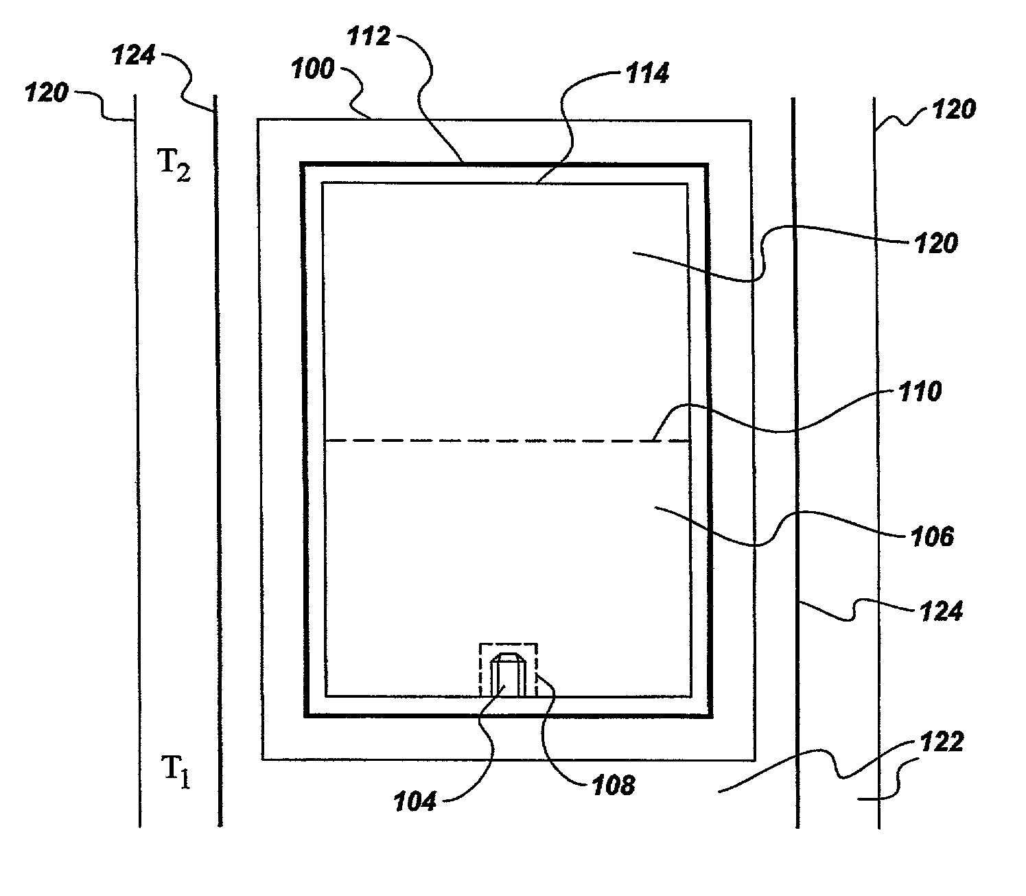
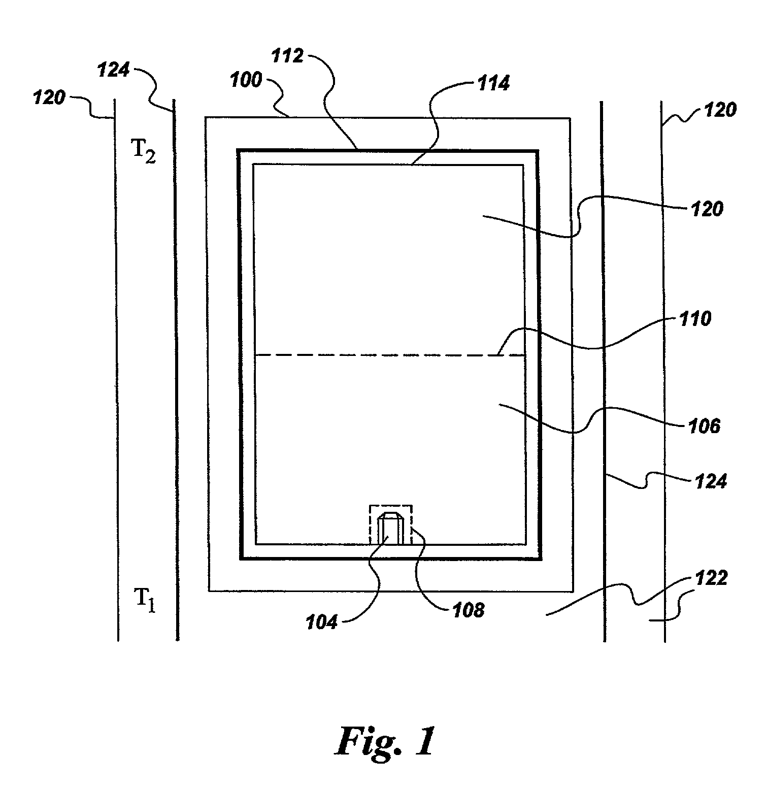
[0021] In one embodiment, a baffle 110 separates source material 102 from the main body of flux 106. Fluid communication between source material 102 and the main body of flux 106 is provided by through holes (not shown) included in baffle 110. Baffle 110 with through holes has a fractional open area in the range of between about 1% and about 40%. In order to prevent dissolution of the crystalline Group III metal nitride seed 104 prior to the onset of growth, a diffusion barrier 108, such as, but not limited to, a thin foil of a suitable material, such as platinum, tantalum, and the like, may be provided to protect the crystalline Group III metal nitride seed 104. The crystalline Group III metal nitride seed 104 may either be wrapped within diffusion barrier 108, or diffusion barrier 108 may be positioned to separate the seed and a small quantity of flux material 106 from the main body of flux material 106.
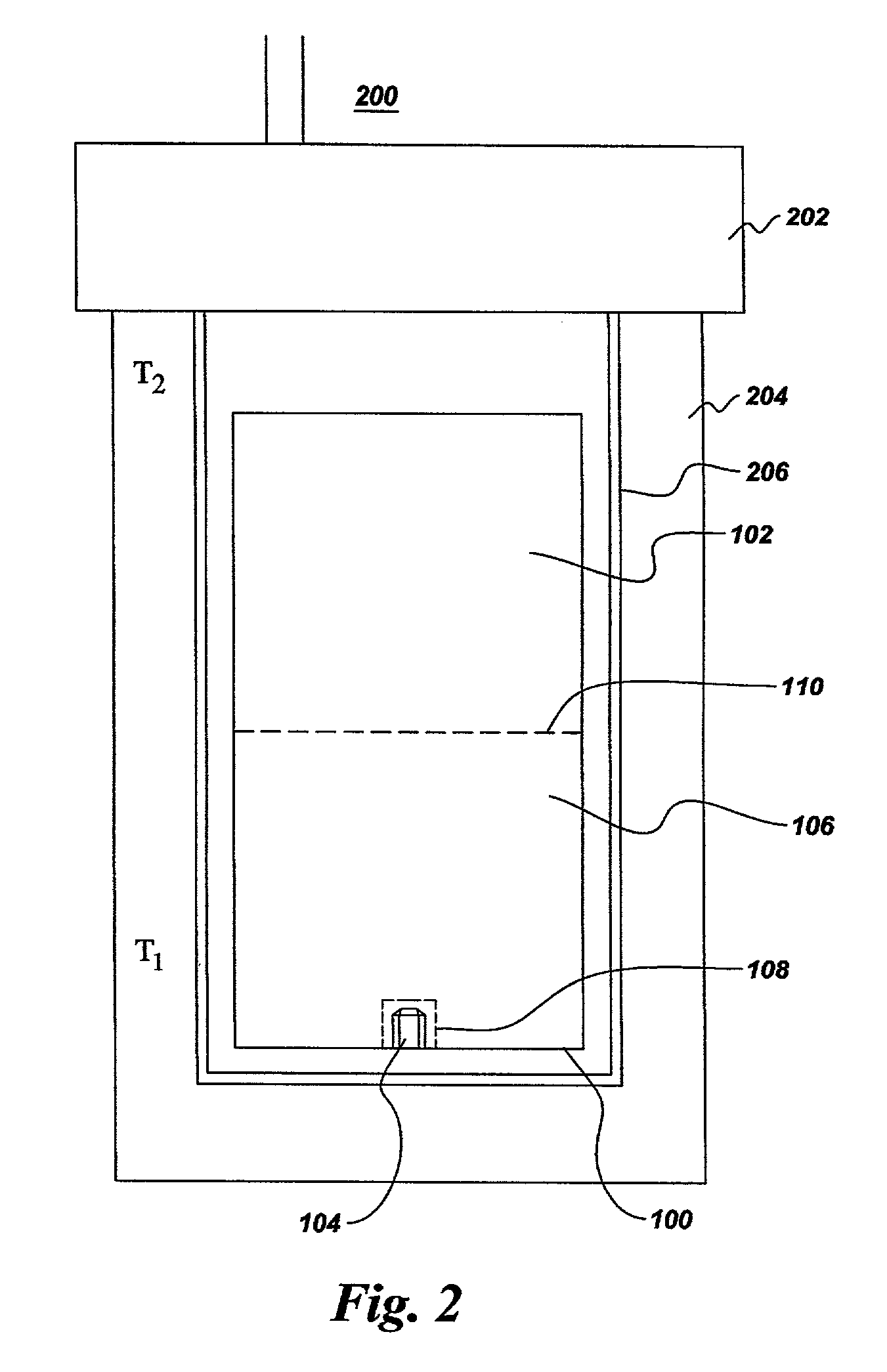
[0027] In yet another embodiment, shown in FIG. 2, the pressure apparatus comprises an autoclave 200 such as, but not limited to, a Morey autoclave, a Tuttle / Roy cold-cone seal autoclave, a modified Bridgman autoclave, a full Bridgman autoclave, a delta ring autoclave, and a Walker-Buehler type autoclave. The at least one Group III metal nitride seed 104, flux 106, and source material 102 are placed in autoclave 200. In one embodiment, a baffle 110 separates source material 102 and the region containing the at least one Group III metal nitride seed 104. In one embodiment, the at least one Group III metal nitride seed 104, flux 106, source material 102, and baffle 110 are placed in reaction vessel 100 prior to insertion into autoclave 200. Reaction vessel 100 and baffle 110 each comprise at least one of: copper; silver; gold; platinum; palladium; iridium; rhodium; ruthenium; osmium; rhenium; iron; nickel; phosphorus; MCxNyOz, where M is at least one metal selected from magnesium, calcium, strontium, barium, aluminum, boron, silicon, titanium, vanadium, chromium, yttrium, zirconium, lanthanum, a rare earth metal, hafnium, tantalum, tungsten, molybdenum, niobium, and combinations thereof, and where 0.ltoreq.x, y, and z.ltoreq.3; pyrophyllite; talc; olivine; calcium carbonate; merylinite clay; bentonite clay; and sodium silicate. In one embodiment, reaction vessel 100 has a melting point of greater than 1600.degree. C. Reaction vessel 100 may be gas tight upon initial filling and sealing, or may become gas tight during processing at high pressure and high temperature. Optionally, an outer liner 206 may be inserted into autoclave 200 to improve chemical inertness.

Problems solved by technology

The performance of these devices, including light emission efficiency, lifetime, and reverse bias current, is often degraded by the presence of threading dislocations, vacancies, and impurities in the active layers and in underlying and overlaying epitaxial layers.
Such devices are typically grown on lattice-mismatched substrates such as sapphire or SiC, resulting in a high concentration of threading dislocations that propagate into the active layer.
The GaN crystals grown under these conditions exhibit varying degrees of quality and are limited in size.
The methods that are currently used to grow gallium nitride crystals are unable to produce large crystals of Group III metal nitrides at acceptable growth rates and that are of high quality.

Method used


Image

  • High pressure high temperature growth of crystalline group III metal nitrides
  • High pressure high temperature growth of crystalline group III metal nitrides
  • High pressure high temperature growth of crystalline group III metal nitrides

Examples


example 2

[0035] Commercially available gallium nitride powder, having the same nominal purity and relatively poor crystallinity as described in Example 1, was compacted into a pill weighing about 1.4 g. Ammonium iodide (NH.sub.4I) powder was compacted into a second pill, weighing 2.6 g. The two pills were placed into a reaction vessel comprising two opposing cups fabricated from hot-pressed boron nitride. The reaction vessel was then placed within a cell and treated at high pressure and high temperature in a temperature gradient cell in a belt-type press apparatus. The pressure was approximately 30 kbar. The temperature of the top of the cell was about 1435.degree. C., and the temperature at the bottom of the cell was about 1360.degree. C. After a treatment time of about 20 hours, the cell was cooled and removed from the press. Residual NH.sub.4I was washed out of the cell with water, leaving residual GaN powder and well-crystallized GaN crystals, having an average diameter of about 0.5 mm, ...

example 3

[0036] Gallium nitride powder was compacted into a pill weighing about 1.25 g. A second pill was compacted from a mixture comprising about 2.6 g of ammonium iodide (NH.sub.4I.) powder and about 0.1 g GaN powder. The two pills were placed into a reaction vessel comprising two opposing cups fabricated from hot-pressed boron nitride. The reaction vessel was then placed within a cell and treated at high pressure and high temperature in a temperature gradient cell in a belt-type press apparatus. The pressure was approximately 40 kbar. The temperature of the top of the cell was about 1450.degree. C., and the temperature at the bottom of the cell was about 1375.degree. C. After a treatment time of 24 hr, the cell was cooled and removed from the press. Residual NH.sub.4I was washed out of the cell with water, leaving residual GaN powder and well-crystallized GaN crystals.

example 4

[0037] Gallium nitride powder was compacted into a pill weighing about 1.25 g. A second pill was compacted from a mixture comprising about 2.4 g of ammonium bromide (NH.sub.4Br) powder and about 0.1 g. GaN powder. The two pills were placed into a reaction vessel comprising two opposing cups fabricated from hot-pressed boron nitride. The reaction vessel was then placed within a cell and treated at high pressure and high temperature in a temperature gradient cell in a belt-type press apparatus. The pressure was approximately 40 kbar. The temperature of the top of the cell was about 1330.degree. C., and the temperature at the bottom of the cell was about 1255.degree. C. After a treatment time of about 16 hr, the cell was cooled and removed from the press. Residual NH.sub.4Br was washed out of the cell with water, leaving residual GaN powder and GaN crystals.


PUM


Abstract

A method of forming at least one single crystal of a Group III metal nitride. The method includes the steps of: providing a flux material and a source material comprising at least one Group III metal selected from the group consisting of aluminum, indium, and gallium, to a reaction vessel; sealing the reaction vessel; heating the reaction vessel to a predetermined temperature and applying a predetermined pressure to the vessel. The pressure is sufficient to suppress decomposition of the Group III metal nitride at the temperature. Group III metal nitrides, as well as electronic devices having a Group III metal nitride substrate formed by the method are also disclosed.

Description

Background of Invention[0001] The invention relates to the growth of crystals of Group III metal nitrides. More particularly, the invention relates to the growth of Group III metal nitride crystals by recrystallization from a flux. Even more particularly, the invention relates to the growth of Group III metal nitride crystals by recrystallization from either a solvent or a melt under high pressure, high temperature conditions.[0002] During the past decade there has been considerable interest in the nitrides of the Group III metals (also referred to hereinafter as "Group III metal nitrides"); namely aluminum nitride (also referred to hereinafter as "AlN"), gallium nitride (also referred to hereinafter as "GaN"), and indium nitride (also referred to hereinafter as "InN") based optoelectronic devices, including, for example, light emitting diodes (LEDs) and laser diodes (LDs). The active layers in such devices typically comprise solid solutions of GaN, AlN, and InN and typically includ...

Claims


Application Information

Patent Timeline
IPC IPC(8): C30B9/00C30B9/06C30B29/38
CPCB82Y10/00B82Y30/00C30B9/00Y10T117/1052C30B29/406C30B7/00Y10T117/1096C30B29/403C30B29/40
Inventor D'EVELYN, MARK PHILIPWEBB, STEVEN WILLIAMVAGARALI, SURESH SHANKARAPPAKADIOGLU, YAVUZPARK, DONG-SILCHEN, ZHENG
Owner SLT TECH
Learn More