Li-ion battery and battery active components on metal wire

a technology of lithium ion batteries and active components, which is applied in the field of rechargeable batteries and rechargeable battery components, can solve the problems of failing to provide a small scale battery with an enlarged area for ion exchange, and achieve excellent cycle and calendar life, high discharge depth, and excellent performance characteristics

Inactive Publication Date: 2015-03-31
KALPTREE ENERGY
View PDF36 Cites 11 Cited by
  • Summary
  • Abstract
  • Description
  • Claims
  • Application Information

AI Technical Summary

Benefits of technology

[0009]Embodiments of the present invention include a battery component that uses a long circular cross-sectional metal wire as a substrate for an electrode in a solid state battery. Thin films on the wire can form a cathode, anode, and electrolyte. We define such a battery as energy wire and the embodiments result in battery structures that, for example, combine excellent performance characteristics of a solid state battery (excellent cycle and calendar life, high depth of discharge, rapid charging rate) with the high energy capacity of a traditional battery fabricated using powder based active materials. The metal wire substrate can perform as a current collector in an electrochemical cell. One embodiment of the invention includes, for example, a low cost method of manufacturing an amorphous three dimensional porous silicon-carbon composite anode active material. One embodiment describes a method where a porous anode structure is created. In an embodiment, an innovative low cost annealing technique to heat treat the deposited cathode material is provided to create desired crystalline as well as porosity of structure. Description of fabricating a high density battery is provided allowing formation of a damage tolerant battery. Further understanding of the nature and advantages of the embodiments of the present invention may be realized by reference to the latter portions of the specification and attached drawings.

Problems solved by technology

Among the disadvantages of these batteries and battery components is that they fail to provide a small scale battery with an enlarged area for ion exchange.

Method used


Image

  • Li-ion battery and battery active components on metal wire
  • Li-ion battery and battery active components on metal wire
  • Li-ion battery and battery active components on metal wire

Examples


Embodiment Construction

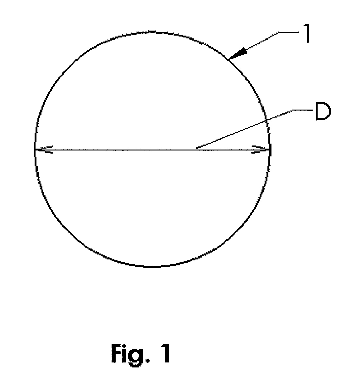
[0043]An embodiment of the present invention relates to the manufacturing of a solid state Li-ion battery on a conductive metal wire substrate, with diverse materials for the cathode, anode, electrolyte and current collector, all associated with the wire. FIG. 1 depicts a circular cross-sectional area of metal wire substrate 1. The metal wire 1 works as a current collector with a diameter D, having a range from 5 micron to 500 micron. Prior to deposition, metal wire can be clean as well as textured to a desired surface roughness using mechanical methods such as bead blasting or chemical methods such as a chemical etching method in order to enhance mechanical and chemical bonding between electrode coating and substrate. Having electrodes with circular cross-section, provides an increase in surface area compared to flat rectangular metal sheet or foil electrodes in traditional electrode fabrication. An increase in surface area coupled with an decrease in anode film thickness provides ...


PUM

PropertyMeasurementUnit
diameteraaaaaaaaaa
diameteraaaaaaaaaa
thicknessesaaaaaaaaaa

Abstract

A battery on a conductive metal wire and components of a battery on a conductive metal wire of circular cross section diameter of 5-500 micrometers and methods of making the battery and battery components are disclosed. In one embodiment, the battery features a porous anode or cathode layer which assist with ion exchange in batteries. Methods of forming the porous anode or cathode layer include deposition of an inert gas or hydrogen enriched carbon or silicon layer on a heated metal wire followed by annealing of the inert gas or hydrogen enriched carbon silicon layer. Energy storage devices having bundles of batteries on wires are also disclosed as are other energy storage devices.

Description

CROSS-REFERENCE TO RELATED APPLICATIONS[0001]This application claims the benefit of priority from U.S. Provisional Application No. 61 / 569,228 filed on Dec. 10, 2011, U.S. Provisional Application No. 61 / 587,632 filed on Jan. 17, 2012, and U.S. Provisional Application No. 61 / 587,659 filed on Jan. 18, 2012, all of which are hereby incorporated by reference.FIELD OF THE INVENTION[0002]The invention pertains in general to batteries and, in particular, to rechargeable batteries and rechargeable battery components, principally electrodes, and methods for making fail-safe damage tolerant rechargeable batteries and rechargeable battery components.BACKGROUND[0003]The demand for efficiency improvements in energy storage systems is driving the development of batteries with higher energy density, increased depth of discharge, a longer cycle life and a lighter, flexible form factors. Most current research effort is directed towards Li-ion batteries (LIBs) because of their inherent higher energy d...

Claims


Application Information

Patent Timeline
Patent Type & Authority Patents(United States)
IPC IPC(8): H01M4/70H01M4/76H01M6/08H01M2/10H01M4/02H01M4/04H01M4/133H01M4/134H01M4/1393H01M4/1395H01M4/36H01M4/38H01M4/587H01M4/66H01M4/75H01M10/04H01M10/0525H01M10/058H01M10/0587
CPCH01M10/058H01M10/0587H01M4/0404H01M2/105H01M4/0471H01M4/133H01M4/134H01M4/661H01M4/75H01M10/04H01M10/049H01M10/0525H01M4/1393H01M4/1395H01M4/366H01M4/386H01M4/587H01M2004/021H01M2004/022Y02E60/122H01M50/213Y02P70/50Y02E60/10H01M10/0422H01M4/0428
Inventor UPADHYAYA, DEEPAK
Owner KALPTREE ENERGY
Why Eureka
Try Eureka