Steel fuel conveying pipe

a conveying pipe and steel technology, applied in the field of pipes, can solve the problems of increasing the cost or impossibility of stable material supply, increasing the cost of product realization, increasing the cost, etc., and achieve the effect of significant improvement of reliability and a life of the gasoline direct-injection engine system

Active Publication Date: 2015-04-21
USUI KOKUSAI SANGYO KAISHA LTD
View PDF25 Cites 0 Cited by
  • Summary
  • Abstract
  • Description
  • Claims
  • Application Information

AI Technical Summary

Benefits of technology

[0026]According to the present invention, such an industrially-significant effect can be achieved that corrosion of the inside of a fuel conveying pipe due to a corrosive factor contained in gasoline (fuel) fed from a high-pressure pump to a direct-injection rail provided with an injector under a high pressure is prevented excellently, and reliability and a life of a gasoline direct-injection engine system are significantly elevated.

Problems solved by technology

However, the stainless pipe which has been subjected to plastic working or joining working includes the following problems:
Therefore, product-working conditions, materials, product specifications are limited by these problems, which results in not only increase in cost or impossibility of stable material supply due to addition of steps or requirements of high precision, but also impossibility of product realization.
However, on the contrary, of course, in addition to such a point that cost increases due to the thickening of a film or the complexity, there is also such a case that breaking (cracking) or separation (delamination) of a plated film occurs due to lowering of a film strength or adhesion strength with a base material, and the barrier performance rather lowers and the corrosion resistance becomes poor so that the required performances cannot be satisfied and a product cannot be realized.
As the countermeasure to the above problem, it is thought to apply anti-rust plating having a sacrifice anticorrosion mechanism of Zn series or Al series excellent in salt damage resistance to an inner surface of the steel pipe, but occurrence of such a new problem is concerned that because the anti-rust plating has a sacrifice anticorrosion function, Zn or Al which is an anti-rust plating component is eluted in corrosive fuels as ions so that the eluted ions raise various adverse effects at various sections of an internal combustion engine.

Method used


Image

  • Steel fuel conveying pipe
  • Steel fuel conveying pipe
  • Steel fuel conveying pipe

Examples


example 1

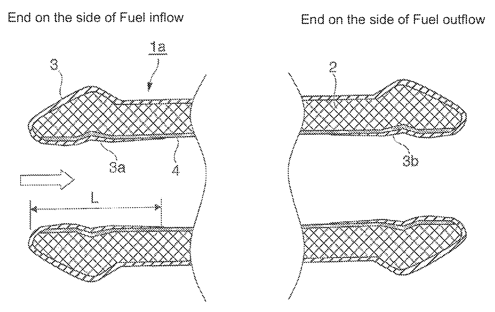
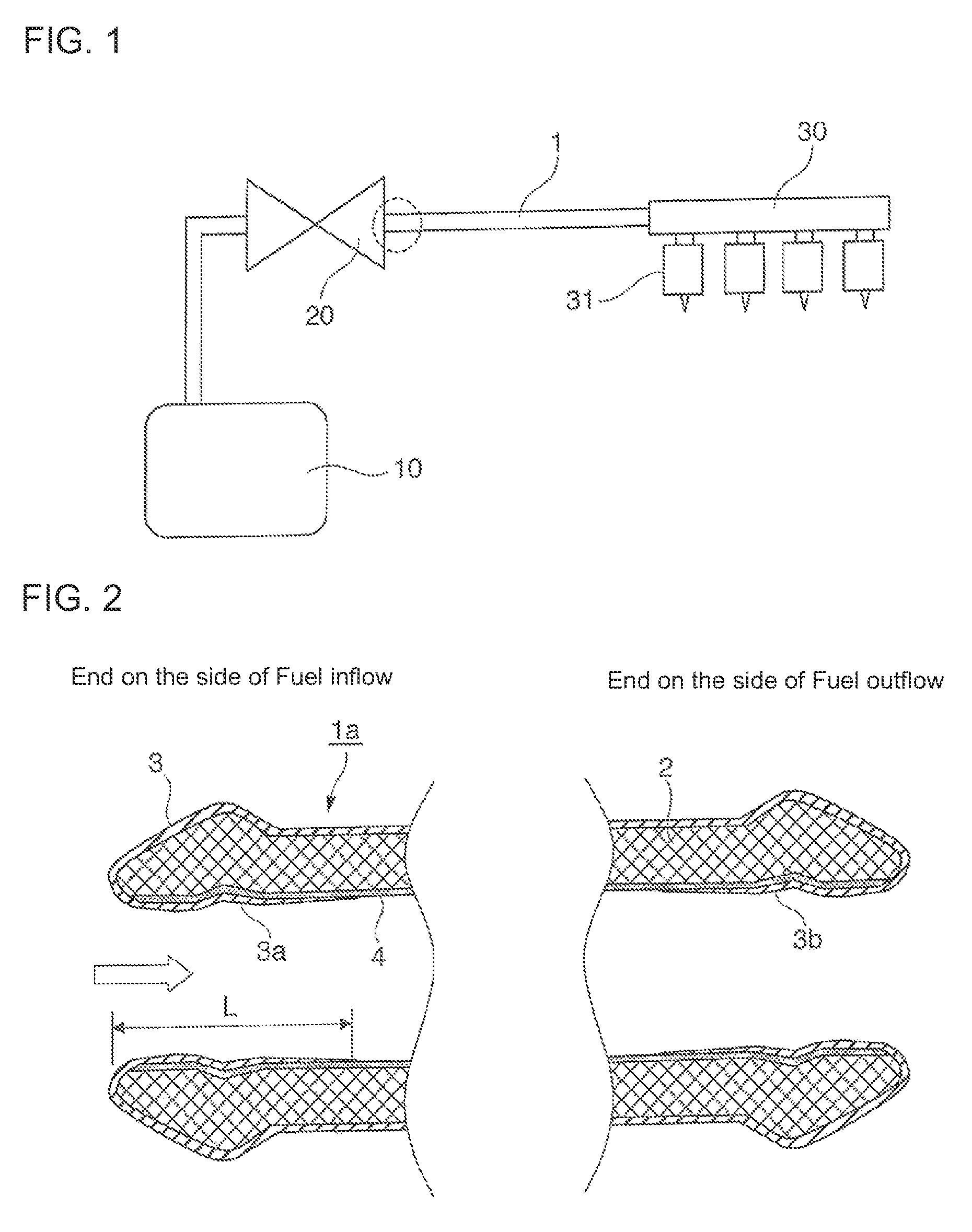
[0089]In the fuel conveying pipe 1a of the present invention having the structure shown in FIG. 2, a steel pipe for high pressure having an inner diameter of 5 mm (D=5 mm) was used as the pipe base material 2, the Ni-plated layer 4 was formed by applying Ni plating with a thickness of 10 μm to the whole inner face of the pipe material, and the anti-rust film layers 3a and 3b were then formed by setting a Zn-plated layer as the anti-rust film layer from an end of the pipe, setting the coating distance L of the anti-rust film layer to 10 mm (L=2D=10 mm) and applying Zn plating with a thickness of 0.1 to 8 μm up to the position of the coating distance L, so that a test material of the fuel conveying pipe was manufactured. The corrosion test to corrosive fuel was performed using the test material. The result of the test is shown in Table 1.

example 2

[0090]In the fuel conveying pipe 1a of the present invention having the structure shown in FIG. 2, a steel pipe for high pressure having an inner diameter of 8 mm (D=8 mm) was used as the pipe base material 2, the Ni-plated layer 4 was formed by applying Ni plating with a thickness of 10 μm to the whole inner face of the pipe material, and the anti-rust film layers 3a and 3b were then formed by setting a Zn—Ni layer as the anti-rust film layer from an end of the pipe, setting the coating distance L of the anti-rust film layer to 24 mm (L=3D=24 mm) and applying Zn—Ni alloy-plating with a thickness of 0.1 to 8 μm up to the position of the coating distance L, so that a test material of the fuel conveying pipe was manufactured. The corrosion test to corrosive fuel which was the test liquid was performed using the test material. The result of the test is shown in Table 1.

example 3

[0091]In the fuel conveying pipe 1a of the present invention having the structure shown in FIG. 2, a steel pipe for high pressure having an inner diameter of 3 mm (D=3 mm) was used as the pipe base material 2, a Ni-plated layer with a thickness of 5 μm was provided by non-electrolytic plating of NiP, and the anti-rust film layers 3a and 3b were then formed by setting a Sn—Zn alloy-plated layer as the anti-rust film layer on the inner face, setting the coating distance L of the anti-rust film layer to 9 mm (L=3D=9 mm) and applying Sn—Zn alloy plating with a thickness of 0.1 to 8 μm up to the position of the coating distance L, so that a test material of the fuel conveying pipe was manufactured. The corrosion test to corrosive fuel which was the test liquid was performed using the test material. The result of the test is shown in Table 1.


PUM

PropertyMeasurementUnit
thicknessaaaaaaaaaa
thicknessaaaaaaaaaa
inner diameteraaaaaaaaaa

Abstract

To provide a steel fuel conveying pipe which has high resistance to corrosive fuel and maintains reliability without damaging a direct-injection engine, and connects a high-pressure pump and a direct-injection rail with each other in a gasoline direct-injection engine system, and a fuel conveying pipe suitable as a bypass pipe for coupling direct-injection rails with each other in a V-type gasoline engine. A steel fuel conveying pipe for conveying gasoline is characterized in that a Ni-plated layer is provided on the whole inner circumferential face of the fuel conveying pipe, and an anti-rust film layer composed of a Zn-plated layer and a Zn-based alloy-plated layer is further provided on the Ni-plated layer at at least one end of the fuel conveying pipe.

Description

BACKGROUND OF THE INVENTION[0001]1. Field of the Invention[0002]The present invention relates to a pipe for supplying fuel to an engine in a gasoline direct-injection engine system.[0003]2. Description of the Related Art[0004]In particular, the present invention relates to a pipe having resistance to inferior fuel containing a corrosive component.[0005]In recent years, in a gasoline direct-injection engine system whose development and release to a market have been advanced in an automobile industry for the purpose of reducing environmental load according to fuel consumption improvement, as shown in FIG. 1, a pipe 1 for supplying fuel (gasoline) to a direct-injection rail 30 of an engine (not shown) from a fuel tank 10 via a pump 20 has been demanded to have pressure resistance and air tightness higher than those of an existing multi point injection (MPI) engine (see Japanese Patent Application Laid-Open No. 2006-152852, Japanese Patent Application Laid-Open No. 2002-54534, and the l...

Claims


Application Information

Patent Timeline
Patent Type & Authority Patents(United States)
IPC IPC(8): F16L9/02F02M55/02F16L58/08
CPCF16L9/02F02M55/02F16L58/08F02M2200/05F02M2200/9038Y10T428/12486Y10T428/12799Y10T428/12937F02M37/00
Inventor TAKAGI, KAZUO
Owner USUI KOKUSAI SANGYO KAISHA LTD
Why Eureka
Try Eureka