
Biosensors including metallic nanocavities

a nanocavity and biosensor technology, applied in the field of evanescent wave type biosensors or biomolecular assays, can solve the problems of unsuitable quantitative assay techniques, unsatisfactory nanostructures, and inability to isolate the background produced by unbound species, so as to reduce the amount of reagents and increase the homogeneity of samples

Inactive Publication Date: 2015-04-21
THE UNIV OF UTAH
View PDF36 Cites 11 Cited by
  • Summary
  • Abstract
  • Description
  • Claims
  • Application Information

AI Technical Summary

Benefits of technology

The patent describes a system for detecting analytes using nanocavities on a metallic film. The nanocavities are designed to enhance the detection of fluorescence by optimizing the coupling of incident light into surface modes on the metallic film. The system also includes a delivery system for recycling samples through the system multiple times to improve detection of low analyte concentrations or in small samples. The use of a sequential delivery system, sample recirculation, sample flow facilitation, or any combination thereof may reduce the amount of reagent required for detecting an analyte in a sample.

Problems solved by technology

One of the major drawbacks of these surface-enhanced techniques is that the nanostructure is disordered (but sometimes with fractal order) such that the fluorescence or Raman enhancement factors are spatially-varying, as evidenced by “hot-spots” on the surface (V. M. Shalaev, R. Botet, J. Mercer, and E. B. Stechel, “Optical properties of self-affine thin films,”Phys. Rev. B, vol.
The hot-spot effect may render these techniques unsuitable for quantitative assays, especially in an array format, as the average enhancement over a defined sensing zone may not be very high, and the enhancement from zone to zone may vary.
However, these techniques do not provide complete isolation from background produced by unbound species, as uniform illumination can excite fluorescence from molecules located between nanoparticles, which produce background signals at the detector.
These SPP modes can constructively interfere within the nanocavities, resulting in intensity enhancement (H. J. Lezec and T. Thio, “Diffracted evanescent wave model for enhanced and suppressed optical transmission through subwavelength hole arrays,”Optics Express, vol.
However, many challenges, such as improving sensitivity, accuracy, precision and specificity of the assays, reducing assay time, etc., remain in the field.

Method used


Image

  • Biosensors including metallic nanocavities
  • Biosensors including metallic nanocavities
  • Biosensors including metallic nanocavities

Examples


examples

1. Biosensing Based Upon Molecular Confinement in Metallic Nanocavity Arrays

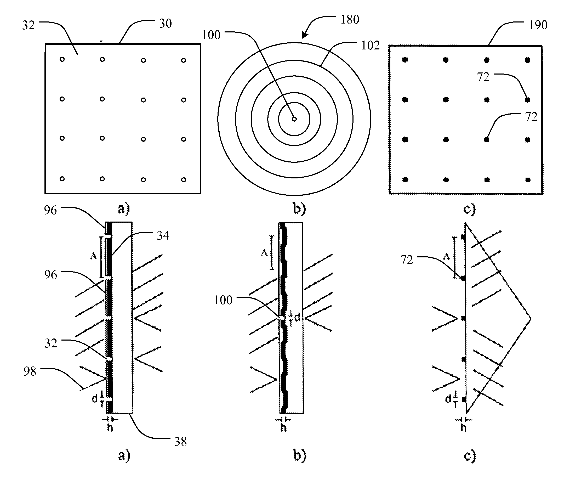
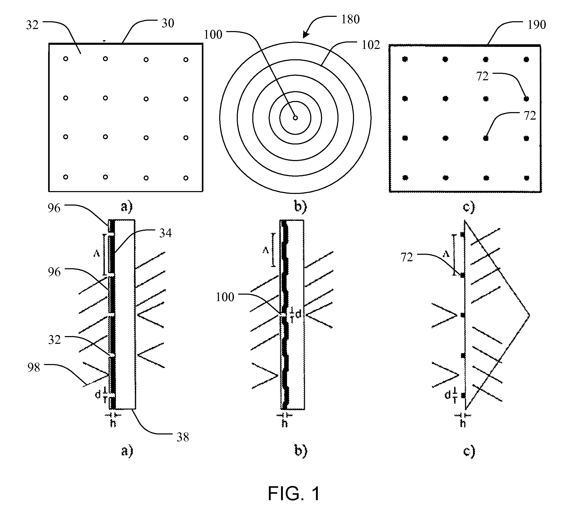
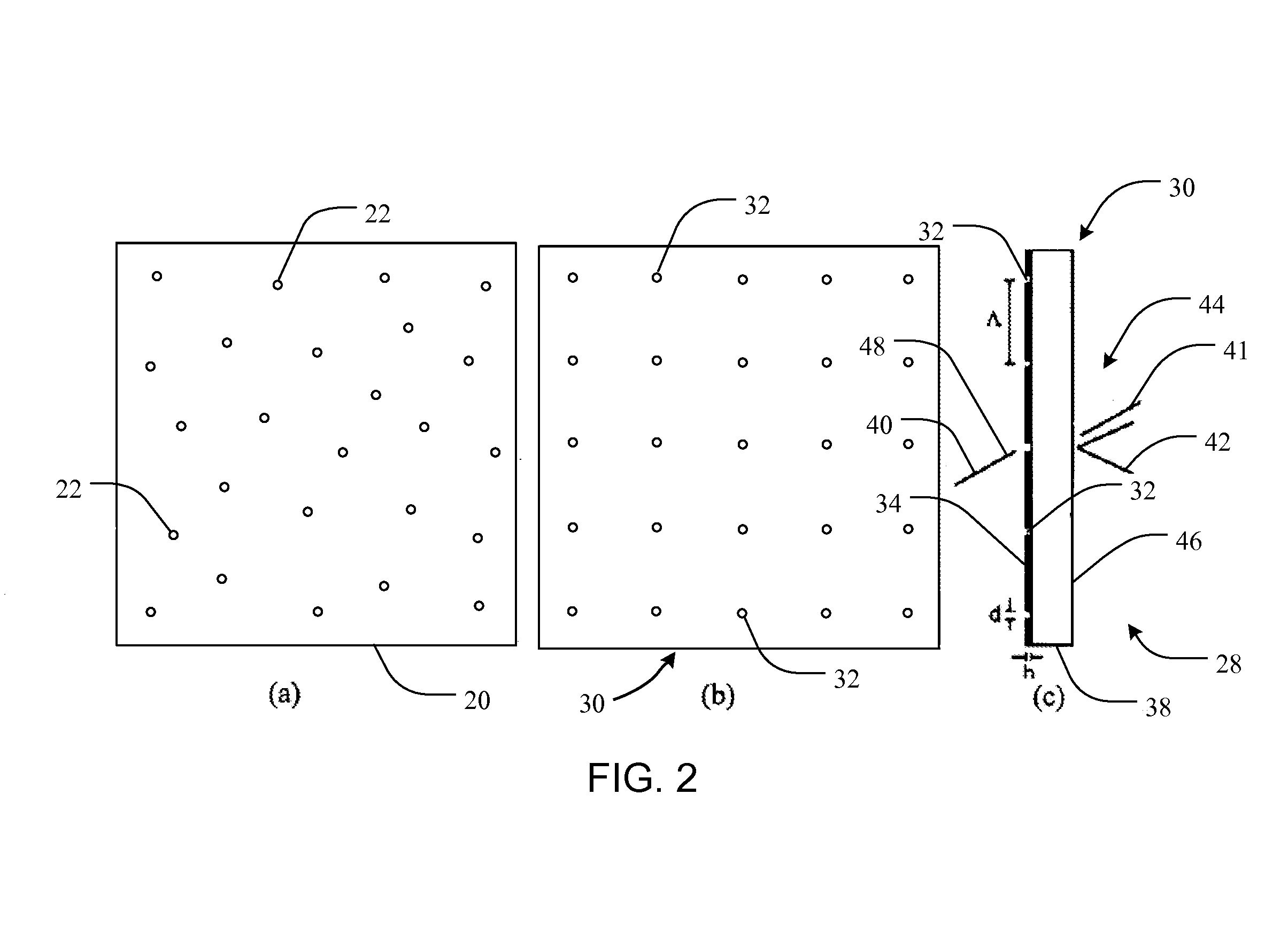
[0065]Liu et al. (Y. Liu, J. Bishop, L. Williams, S. Blair, and J. N. Herron, “Biosensing based upon molecular confinement in metallic nanocavity arrays,”Nanotechnology, vol. 15, pp. 1368-1374, 2004) describes the basis for an affinity biosensor platform in which enhanced fluorescence transduction occurs through the optical excitation of molecules located within metallic nanocavities. The contents of Liu et al. are hereby incorporated herein, in their entireties, by this reference. The nanocavities of Liu et al. are about 200 nm in diameter, are arranged in periodic or random two-dimensional arrays, and are fabricated in 70 nm thick gold films by e-beam lithography using negative e-beam resist. It has been shown that both periodic and randomly placed metallic nanocavities can be used to enhance the fluorescence output of molecules within the cavities by about a factor of ten. In addition, the platform provid...


PUM

PropertyMeasurementUnit
widthaaaaaaaaaa
thicknessaaaaaaaaaa
thicknessaaaaaaaaaa

Abstract

A biomolecular assay includes a substrate with a metallic layer on at least one surface thereof. The metallic film includes nanocavities. The nanocavities are configured to enhance signals that are representative of the presence or amount of one or more analytes in a sample or sample solution, and may be configured to enhance the signal by a factor of about two or more or by a factor of about three or more. Such signal enhancement may be achieved with nanocavities that are organized in an array, randomly positioned nanocavities, or nanocavities that are surrounded by increased surface area features, such as corrugation or patterning, or nanocavities that have quadrilateral or triangular shapes with tailored edge lengths, or with a plurality of nanoparticles. Methods for fabricating biomolecular substrates and assay techniques in which such biomolecular substrates are used are also disclosed.

Description

RELATED APPLICATIONS UNDER 35 U.S.C. §119(e)[0001]This application claims the benefit of U.S. Provisional Patent Application Ser. No. 60 / 705,216, filed Aug. 2, 2005, for “BIOSENSORS INCLUDING METALLIC NANOCAVITIES,” the entire contents of which are hereby incorporated herein by this reference. This application also claims the benefit of U.S. Provisional Patent Application Ser. No. 60 / 795,110, filed Apr. 26, 2006, for “METALLIC NANOCAVITIES CONFIGURED TO PROVIDE OPTIMAL RADIATIVE ENHANCEMENT,” the entire contents of which are hereby incorporated herein by this reference.STATEMENT REGARDING FEDERALLY SPONSORED RESEARCH OR DEVELOPMENT[0002]This invention was made in part with Government support under Contract No. ECS-0134548 awarded by National Science Foundation (NSF) and Contract No. 1R21EB000481-01 awarded by National Institute of Health (NIH). The Government has certain rights in this invention.BACKGROUND OF THE INVENTION[0003]1. Field of the Invention[0004]The invention relates ge...

Claims


Application Information

Patent Timeline
Patent Type & Authority Patents(United States)
IPC IPC(8): C12M1/34B82Y15/00B82Y20/00B82Y30/00G01N21/64G01N21/77G01N33/543G02B5/00
CPCG01N33/54373B82Y15/00B82Y20/00B82Y30/00G01N21/648G01N21/7746G02B5/008G02B2207/101G01N21/6428G01N2021/6439
Inventor BLAIR, STEVEN M.MAHDAVI, FARHADLIU, YONGDONGHERRON, JAMES N.NAHATA, AJAY
Owner THE UNIV OF UTAH
Learn More