Cemented carbide base outer blade cutting wheel and making method

a cutting wheel and cement carbide technology, applied in grinding devices, manufacturing tools, other chemical processes, etc., can solve the problems of shedding and fracture of abrasive grains, heat has a substantial impact on the wear of abrasive grains, and the cutting operation of high-accuracy grains can be substantially saved, and the inspection of cut pieces may be simplified. , the effect of high dimensional accuracy

Active Publication Date: 2015-04-28
SHIN ETSU CHEM IND CO LTD
View PDF12 Cites 3 Cited by
  • Summary
  • Abstract
  • Description
  • Claims
  • Application Information

AI Technical Summary

Benefits of technology

[0030]Using the cemented carbide base outer-diameter blade cutting wheel, an article, typically rare earth sintered magnet block can be cut into pieces at a high dimensional accuracy. Since the cutting wheel can be used over a long term without a need for dressing, in cutting of an article into pieces of high accuracy dimensions, the extra steps which are otherwise required to maintain high-accuracy cutting operation can be substantially saved. In extreme cases, the step of inspecting the dimensions of cut pieces may be simplified. Rare earth magnet pieces having a high dimensional accuracy are obtained at a low cost.

Problems solved by technology

It is believed that shedding and fracture of abrasive grains are caused by impacts upon cutting because abrasive grains heavily collide against a workpiece to abrade off the workpiece.
Flattening of abrasive grains at their tip to become coextensive to the surface of the grain-retaining matrix is caused by not only impacts upon cutting, but also local generation of high heat whereby grains are worn or consumed.
The heat generated during working causes chemical reaction to occur between the metal element in the workpiece and grains (diamond), and as a result, grains are worn or consumed.
Thus it is not believed hitherto that the cutting heat has a substantial impact on the wear of abrasive grains, especially diamond grains.

Method used


Image

  • Cemented carbide base outer blade cutting wheel and making method
  • Cemented carbide base outer blade cutting wheel and making method
  • Cemented carbide base outer blade cutting wheel and making method

Examples


example 1

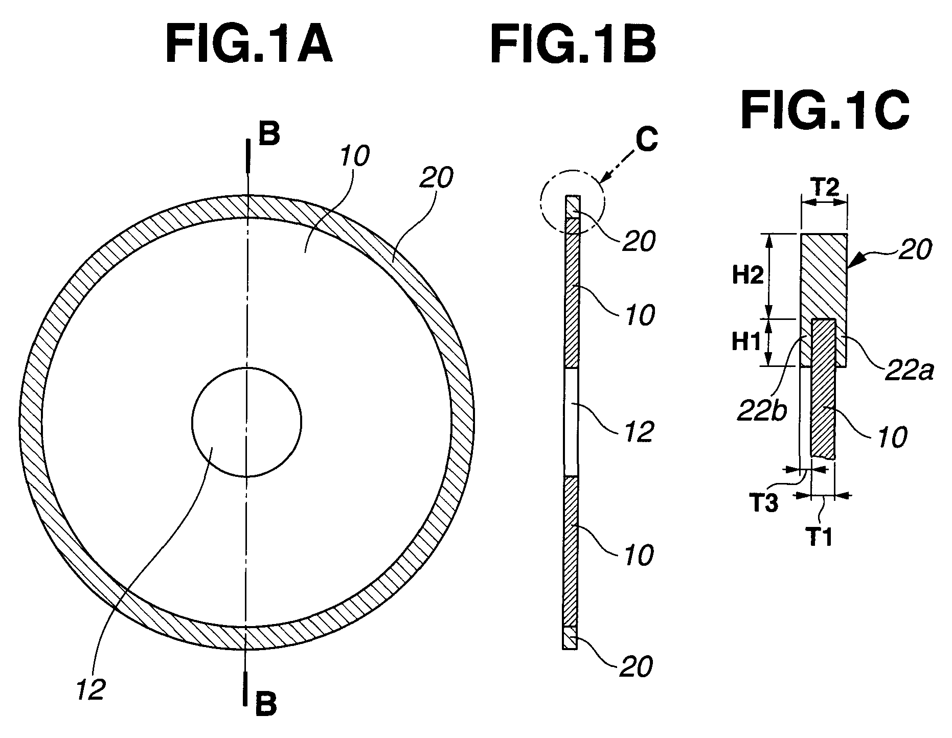
[0122]A cemented carbide consisting of 90 wt % WC and 10 wt % Co was machined into an annular thin disc having an outer diameter of 125 mm, an inner diameter of 40 mm, and a thickness of 0.3 mm, which served as a base. The base had a Young's modulus of 600 GPa and a saturation magnetization of 127 kA / m (0.16 T).

[0123]The cemented carbide base was sandwiched between polyphenylene sulfide (PPS) resin discs having an outer diameter of 123 mm and a thickness of 10 mm so that only a circumferential region of either base surface extending 1.0 mm inward from the outer periphery was exposed. The base was immersed in a commercially available aqueous alkaline solution at 40° C. for 10 minutes for degreasing, washed with water, and immersed in an aqueous solution of 30-80 g / L of sodium pyrophosphate at 50° C. where electrolysis was effected at a current density of 2-8 A / dm2. The base was ultrasonic washed in deionized water and immersed in a sulfamic acid Watts nickel plating bath at 50° C. wh...

example 2

[0128]A cemented carbide consisting of 90 wt % WC and 10 wt % Co was machined into an annular thin disc having an outer diameter of 125 mm, an inner diameter of 40 mm, and a thickness of 0.3 mm, which served as a base.

[0129]The cemented carbide base was sandwiched between PPS discs having an outer diameter of 123 mm and a thickness of 10 mm so that only a circumferential region of either base surface extending 1.0 mm inward from the outer periphery was exposed. The base was immersed in a commercially available aqueous alkaline solution at 40° C. for 10 minutes for degreasing, washed with water, and immersed in an aqueous solution of 30-80 g / L of sodium pyrophosphate at 50° C. where electrolysis was effected at a current density of 2-8 A / dm2. The base was ultrasonic washed in deionized water and immersed in a sulfamic acid Watts nickel plating bath at 50° C. where an undercoat was plated at a current density of 5-20 A / dm2. Thereafter, the base was washed with water.

[0130]A ceramic di...

example 3

[0135]A cemented carbide consisting of 90 wt % WC and 10 wt % Co was machined into an annular thin disc having an outer diameter of 125 mm, an inner diameter of 40 mm, and a thickness of 0.3 mm, which served as a base.

[0136]The cemented carbide base was sandwiched between PPS discs having an outer diameter of 123 mm and a thickness of 10 mm so that only a circumferential region of either base surface extending 1.0 mm inward from the outer periphery was exposed. The base was immersed in a commercially available aqueous alkaline solution at 40° C. for 10 minutes for degreasing, washed with water, and immersed in an aqueous solution of 30-80 g / L of sodium pyrophosphate at 50° C. where electrolysis was effected at a current density of 2-8 A / dm2. The base was ultrasonic washed in deionized water and immersed in a sulfamic acid Watts nickel plating bath at 50° C. where an undercoat was plated at a current density of 5-20 A / dm2. Thereafter, the base was washed with water.

[0137]cBN abrasive...


PUM

PropertyMeasurementUnit
inner diameteraaaaaaaaaa

Abstract

An outer blade cutting wheel comprising an annular thin disc base of cemented carbide and a blade section of metal or alloy-bonded abrasive grains on the outer periphery of the base is provided. The abrasive grains are diamond and / or cBN grains having an average grain size of 45-310 μm and a TI of at least 150. The blade section includes overlays having a thickness tolerance (T3max−T3min) of 0.001 mm to 0.1×T2 mm. The blade section has a roundness (ODmax / 2−ODmin / 2) of 0.001 mm to 0.01×ODmax mm.

Description

CROSS-REFERENCE TO RELATED APPLICATION[0001]This non-provisional application claims priority under 35 U.S.C. §119(a) on Patent Application No. 2011-148045 filed in Japan on Jul. 4, 2011, the entire contents of which are hereby incorporated by reference.TECHNICAL FIELD[0002]This invention relates to a cemented carbide base outer-diameter blade cutting wheel suited for sawing rare earth sintered magnet blocks, and a method for preparing the same.BACKGROUND ART[0003]Known in the art are OD (outer diameter) blade cutting wheels comprising a cemented carbide base having an outer periphery to which diamond and / or cBN abrasive grains are bonded with phenolic resins or metal plating. The sawing process using such cutting wheels is regarded very useful in the industry because of many advantages including the low price of the cutting tool, a relatively small cutting allowance, a good dimensional accuracy of cut pieces, and a relatively high machining speed. Since the cutting wheels are best s...

Claims


Application Information

Patent Timeline
Patent Type & Authority Patents(United States)
IPC IPC(8): B24D18/00B24D3/06B24D5/12
CPCB24D3/06B24D5/12B28D5/022B24D3/28B23P15/40B24D5/06
Inventor KASASHIMA, MASAKIMINOWA, TAKEHISAMAEGAWA, HARUKAZUNAGASAKI, YOSHIFUMI
Owner SHIN ETSU CHEM IND CO LTD
Why Eureka
Try Eureka