Digital Protection control system and digital protection control apparatus

a control system and digital protection technology, applied in the direction of emergency protection circuit arrangement, emergency protection arrangement details, electrical devices, etc., can solve problems such as failure to remove, and achieve the effect of easy expansion of terminals, easy addition, and easy expansion

Active Publication Date: 2015-08-25
HITACHI LTD
View PDF16 Cites 0 Cited by
  • Summary
  • Abstract
  • Description
  • Claims
  • Application Information

AI Technical Summary

Benefits of technology

[0014]Through a configuration according to the present invention, a protection control system for a multiple-terminal transmission line capable of easily expanding terminals can be constructed while securing a sampling synchronization from a power system. Accordingly, for example, a terminal can be easily added due to dispersion of power supply, or a terminal of the transmission line can be easily added due to generation of a new load.

Problems solved by technology

When a section containing the failure point is separated from the left trouble-free power system through tripping of a breaker, a failure is removed.

Method used


Image

  • Digital Protection control system and digital protection control apparatus
  • Digital Protection control system and digital protection control apparatus
  • Digital Protection control system and digital protection control apparatus

Examples


first embodiment

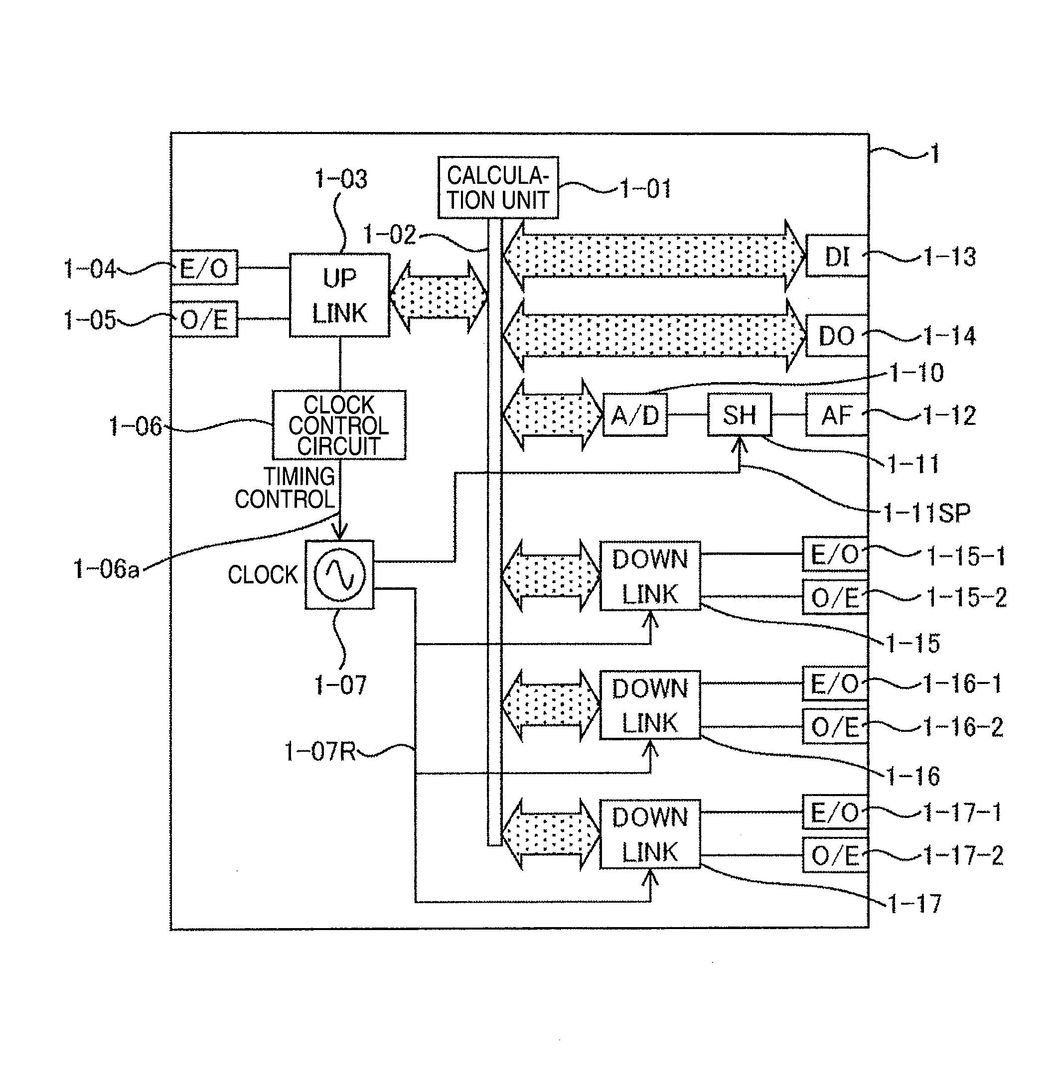
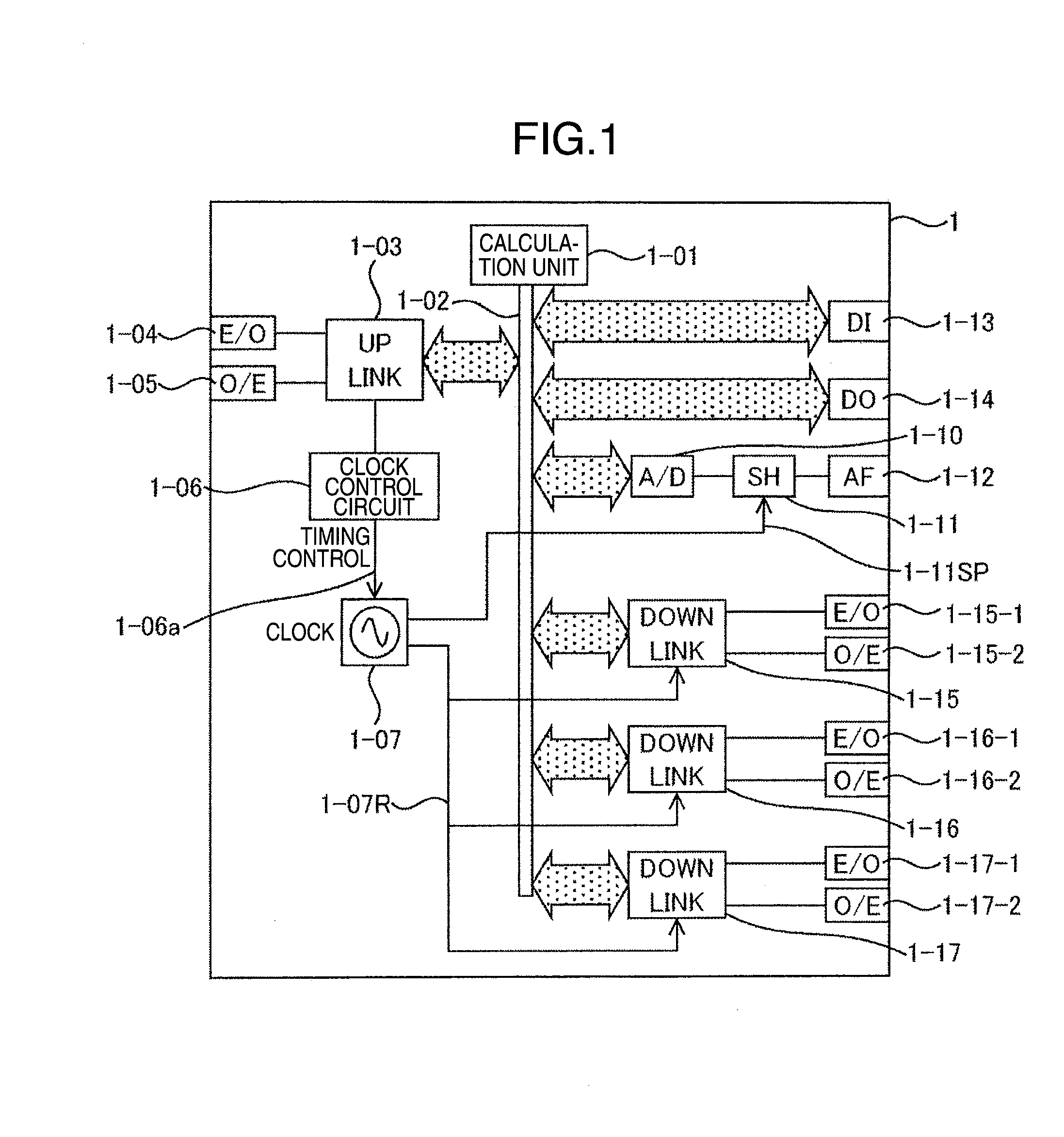
[0028]FIG. 1 illustrates a configuration example of a relay terminal device which constitutes a relay system according to the present embodiment. A terminal station 1 being a terminal device of a protection relay generates a sampling reference signal 1-11SP based on a clock of its own station by using a reference clock unit, shown as “C.L.” in the drawing, 1-07. An uplink 1-03 being a transmission unit for an uplink station includes a transmission interface unit 1-04 and a reception interface unit 1-05. In the case where a terminal station connected to a site beyond the transmission interface unit 1-04 and the reception interface unit 1-05 is located, the uplink 1-03 is provided on a clock control circuit, shown as “C.C.C.” in the drawing, 1-06 for synchronizing its own station with clock timing of the upper station.

[0029]In the case where this communication partner is present, the clock control circuit 1-06 gives to the reference clock unit 1-07 a timing control, shown as “T.C.” in...

second embodiment

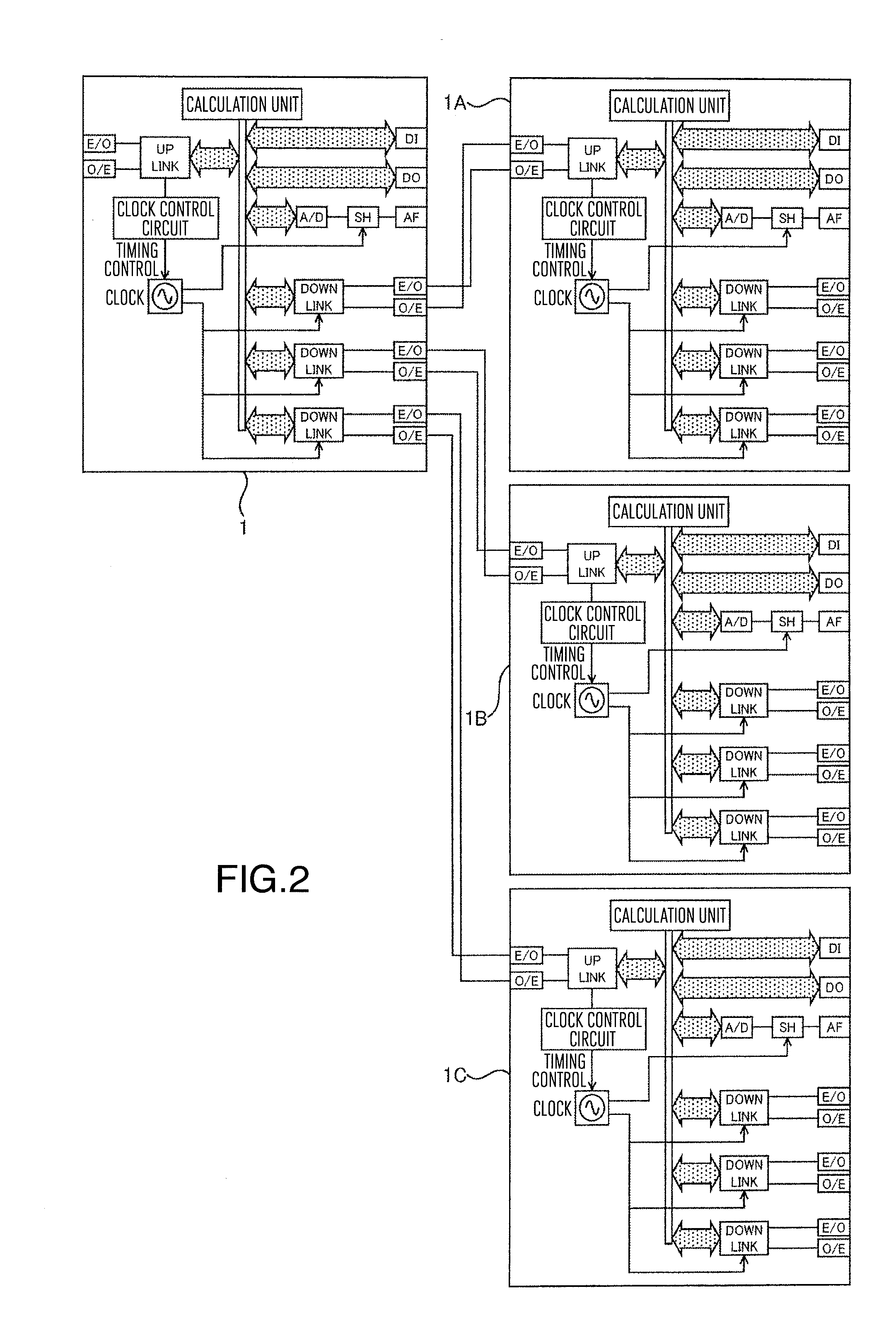
[0067]In the present embodiment, eve if a terminal station is communication-connected to multiple stages, sampling synchronization of all terminals is secured. An example in which a section protection system applicable to a multiple-section transmission line is constructed as its application is illustrated in FIG. 11.

[0068]Section electric power stations 11-A, 11-B, 11-C, 11-D, and 11-E constituting a transmission network are electric power stations of switchyards building a transmission network, and may be transformer stations having switching equipment. In the present embodiment, the electric power stations 11-A to 11-E are constituted through one transmission line. Here, 11-S01 is set as a transmission line section 1, 11-S02 is set as a transmission line section 2, 11-S03 is set as a transmission line section 3, and 11-S04 is set as a transmission line section 4. Current information units S01A and S01B are those of both ends of the section 1, and taken from a sensor or CT. In the...

third embodiment

[0077]As described also in the present embodiment, in principle, a protection relay device for a transmission line current differential needs current information on a partner terminal station in which sampling synchronization is secured and has a communication function. However, an optical interface for communication composed of laser diodes and photodiodes has a limitation to a transmission distance without a relay device because of the attenuation of optical signals due to optical fibers.

[0078]Therefore, conventionally, a signal is repeated through a special communication device, thus implementing a long distance correspondence. Communication devices are constructed by signal multiplexing devices and developed as a device for telephone or data transmission. However, through the progress of IP technology, the communication devices are required to be suitable for, for example, a PDH network to a high-speed packet communication, than a conventional cyclic communication network. For t...


PUM


Abstract

Disclosed are a digital protection control system and a digital protection control apparatus, wherein the digital protection control apparatus can easily be made to have more terminals, even when the number of terminals of a power transmission line increases. The digital protection control system has, as terminal stations thereof, a reference station that is to become the reference point for the sampling time at which power grid current information is to be taken in, tail-end stations that take in power grid current information from the power grid system, and intermediate stations that are connected between the reference station and the tail-end stations via transmission paths. The intermediate station is provided with an uplink transmission unit that is connected to a transmission path at the reference station side thereof, and a plurality of downlink transmission units that are connected to transmission paths at the tail-end station side thereof. The intermediate station also has the time thereof to be subordinate to the time of the terminal station connected to the uplink transmission unit thereof, and the time of the terminal stations connected to the downlink transmission units thereof are made to be subordinate to the intermediate station, with the time thereof used as reference time.

Description

TECHNICAL FIELD[0001]The present invention relates to a digital protection control system and digital protection control apparatus which detect a failure and abnormality occurring in a power system.BACKGROUND ART[0002]Against a failure occurring in a power system so-called short circuit failure or earth faulting, a protection relay device installed in each element such as a transmission line, transformer, bus, and generator forming a power system operates with respect to a failure occurring within its territory. When a section containing the failure point is separated from the left trouble-free power system through tripping of a breaker, a failure is removed. At present, there goes mainstream a digital protection relay in which current information or voltage information of power system is digitized and algorithm for determining a system failure is realized through software process.[0003]As its function, hopefully, a power protection relay correctly detects a failure within a previou...

Claims


Application Information

Patent Timeline
Patent Type & Authority Patents(United States)
IPC IPC(8): H02H3/00H02H1/00H02H7/26H02H7/00
CPCH02H1/0061H02H1/0084H02H7/261
Inventor KOMATSU, CHIKASHIKIDO, MITSUYASUYOSHIDA, SHOJITAKAMI, KAZUHISA
Owner HITACHI LTD
Why Eureka
Try Eureka