
Targeted pretreatment and selective ring opening in liquid-full reactors

a liquid-full reactor and selective ring technology, applied in the direction of hydrocarbon oil treatment products, aromatic hydrocarbon hydrogenation, refining to eliminate heteroatoms, etc., can solve the problems of few options for their use, low commercial value of options available, and inability to directly blend oil into diesel fuel

Active Publication Date: 2015-09-22
REFINING TECH SOLUTIONS LLC
View PDF34 Cites 10 Cited by
  • Summary
  • Abstract
  • Description
  • Claims
  • Application Information

AI Technical Summary

Benefits of technology

The patent describes a two-stage treatment process for hydrocarbon feeds. The first stage aims to remove nitrogen, sulfur, and aromatics from the feed to prevent damage to the second catalyst in the process. The second stage selectively opens rings to improve the feed's cetane value and reduce its density. The technical effect of this two-stage treatment is an improved quality of the treated hydrocarbon feed.

Problems solved by technology

However, such oils cannot be directly blended into today's diesel fuels because of their high sulfur content, high nitrogen content, high aromatics content (particularly high polyaromatics), high density, and low cetane value.
Today, producers of heavy hydrocarbon mixtures have few options for their use, and the options available have relatively low commercial value.
However, the sulfur contents of these hydrocarbons may limit their use due to recent regulations calling for more stringent heating oil sulfur standards.
If the nitrogen content is too high in the hydrocarbon mixture going into the hydrocracking process, the zeolitic hydrocracking catalyst may be poisoned.
These units are expensive, require large quantities of hydrogen, much of which must be recycled through expensive hydrogen compressors, and result in significant coke formation on the catalyst surface and catalyst deactivation.
However, Thakkar et al. use traditional trickle bed reactors, which require large quantities of hydrogen and large process equipment such as a large gas compressor for hydrogen gas circulation.
Thus, hydrogen gas is lost from the reactor effluent, which may be significant, as Kokayeff teaches adding hydrogen well above the hydrogen saturation limit of the liquid.

Method used


Image

  • Targeted pretreatment and selective ring opening in liquid-full reactors
  • Targeted pretreatment and selective ring opening in liquid-full reactors

Examples


examples

Analytical Methods and Terms

[0051]ASTM Standards. All ASTM Standards are available from ASTM International, West Conshohocken, Pa., www.astm.org.

[0052]Amounts of sulfur, nitrogen and basic nitrogen are provided in parts per million by weight, wppm.

[0053]Total Sulfur was measured using ASTM D4294 (2008), “Standard Test Method for Sulfur in Petroleum and Petroleum Products by Energy Dispersive X-ray Fluorescence Spectrometry,” DOI: 10.1520 / D4294-08 and ASTM D7220 (2006), “Standard Test Method for Sulfur in Automotive Fuels by Polarization X-ray Fluorescence Spectrometry,” DOI: 10.1520 / D7220-06

[0054]Total Nitrogen was measured using ASTM D4629 (2007), “Standard Test Method for Trace Nitrogen in Liquid Petroleum Hydrocarbons by Syringe / Inlet Oxidative Combustion and Chemiluminescence Detection,” DOI: 10.1520 / D4629-07 and ASTM D5762 (2005), “Standard Test Method for Nitrogen in Petroleum and Petroleum Products by Boat-Inlet Chemiluminescence,” DOI: 10.1520 / D5762-05.

[0055]Aromatic content...

examples 1-3

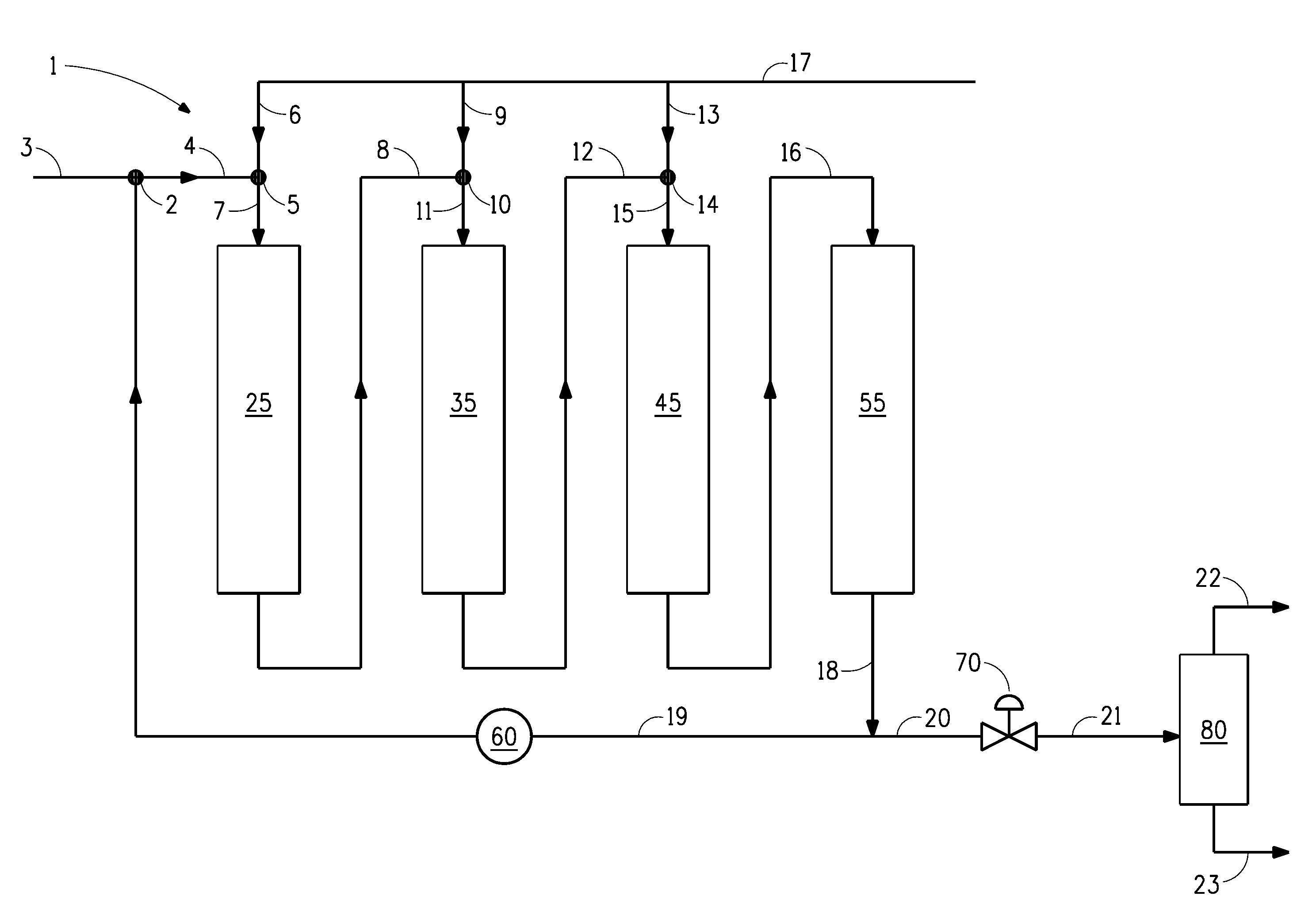
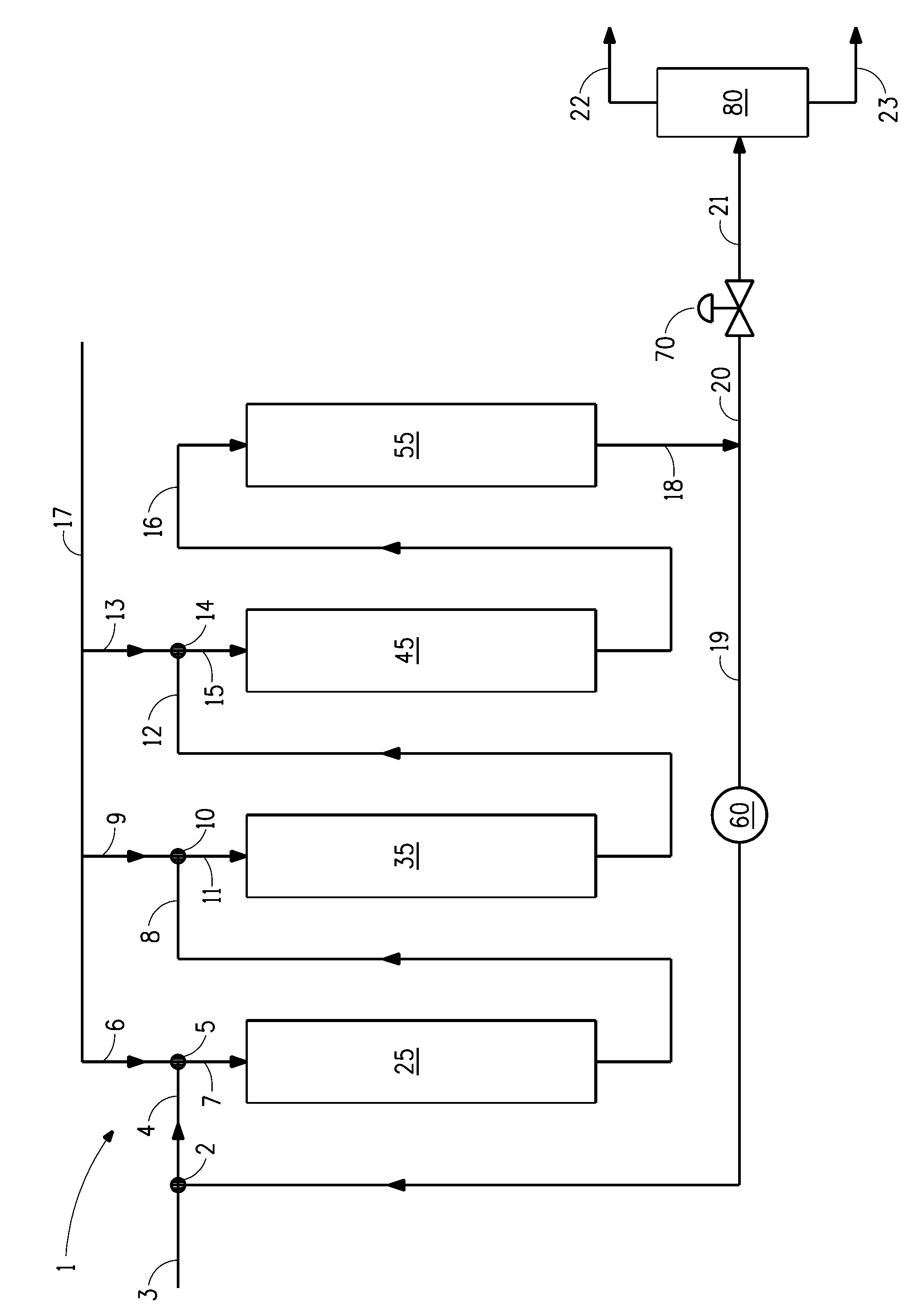
[0068]The properties of a gas oil (GO) from a commercial refiner are shown in Table 1. The GO was hydroprocessed in an experimental pilot unit containing four fixed bed reactors in series. Each reactor was of 19 mm (¾″) OD 316 L stainless steel tubing and about 61 cm (24″) in length with reducers to 6 mm (¼″) on each end. Both ends of the reactors were first capped with metal mesh to prevent catalyst leakage. Below the metal mesh, the reactors were packed with layers of 1 mm glass beads at both ends. Catalyst was packed in the middle section of the reactor.

[0069]

TABLE 1Properties of Gas Oil used in Examples 1 and 2PropertyUnitValueSulfurwppm19900Nitrogenwppm935Density at 15.6° C. (60° F.)g / ml0.9198API Gravity22.2Boiling Point Distribution %° C.IBP 24953281035620386304074042550442604617048180504905339555499583FBP 591IBP = Initial boiling pointFBP = Final boiling point

[0070]The first two reactors, Reactors 25 and 35, were used for targeted pretreatment (“PT”). Reactors 1 and 2 contain...

examples 4-8

[0079]A 100% light cycle oil (LCO) from a FCC unit of a petroleum refinery having the properties set forth in Tables 3 and 4 was hydroprocessed in the pilot unit described in Example 1, with certain modifications.

[0080]

TABLE 3Properties of Light Cycle Oil used in Examples 4 to 8Preferred PropertyUnitMeasuredDiesel SpecsSulfur contentwppm4980Nitrogen contentwppm671Density at 15.6° C.g / ml0.94090.860Density at 20° C.g / ml0.9377API Gravityg / ml18.7Refractive Index at 20° C.1.544Bromine Numberg / 100 g 5.0Cetane Index24.6Increase >+12Aromatic contentMonoaromaticswt %22.7Polyaromaticswt %45.6Total Aromatics wt %68.3

[0081]

TABLE 4Boiling Point Distribution of LCO used in Examples 4 to 8Simulated distillation,Boiling Pointwt %° C. (° F.)Initial Boiling Point (IBP)104 (218) 5%205 (401)10%237 (459)20%260 (500)30%269 (516)40%284 (544)50%297 (566)60%310 (589)70%329 (625)80%346 (655)90%362 (684)95%370 (699)99%394 (741)End Point (EP)414 (778)

[0082]Tables 3 and 4 show that, compared to a diesel sample,...


PUM

PropertyMeasurementUnit
end boiling pointaaaaaaaaaa
temperatureaaaaaaaaaa
densityaaaaaaaaaa

Abstract

A process for hydroprocessing hydrocarbons in a combined targeted pretreatment and selective ring-opening unit wherein the targeted pretreatment comprises at least two stages in a single liquid recycle loop. The process operates as a liquid-full process, wherein all of the hydrogen dissolves in the liquid phase. Heavy hydrocarbons and light cycle oils can be converted in the process to provide a liquid product having over 50% in the diesel boiling range, with properties to meet use in low sulfur diesel.

Description

FIELD OF THE INVENTION[0001]The present invention relates to a process for hydroprocessing hydrocarbon feeds in liquid-full reactors with a single liquid recycle loop.BACKGROUND OF THE INVENTION[0002]Global demand for diesel, particularly for ultra-low-sulfur-diesel (ULSD) has risen quickly with increased growth of transportation fuels and a decrease in the use of fuel oil. Regulations for transportation fuels have been established to substantially lower the sulfur levels in diesel fuels. There are other pending rules calling to reduce the sulfur content in off-road diesel as well. Thus, there is a growing need for hydrocarbon feeds to use as feedstocks for producing diesel, including ULSD.[0003]A refinery produces a number of hydrocarbon products having different uses and different values. It is desired to reduce production of or upgrade lower value products to higher value products. Two examples of lower value products are cycle oils and heavy hydrocarbons.[0004]Cycle oils have hi...

Claims


Application Information

Patent Timeline
Patent Type & Authority Patents(United States)
IPC IPC(8): C10G65/02C10G45/60C10G65/08C10G69/02C10G45/48C10G65/12C10G45/08C10G45/22C10G45/58
CPCC10G65/12C10G45/08C10G45/22C10G45/48C10G45/58C10G45/60C10G65/08C10G69/02C10G2300/4018C10G2300/4081C10G2300/802C10G2400/04C10G65/02
Inventor DINDI, HASANMURILLO, LUIS EDUARDOPULLEY, ALAN HOWARD
Owner REFINING TECH SOLUTIONS LLC
Learn More