Light-emitting arrangement

a technology of light-emitting arrangements and light-emitting phosphors, which is applied in the direction of semiconductor devices for light sources, point-like light sources, lighting and heating apparatus, etc., can solve the problems of additional efficiency loss, loss of device efficiency, and inorganic phosphors suffering from the disadvantage of being relatively expensive, so as to improve the control of the environment

Inactive Publication Date: 2015-10-13
SIGNIFY HLDG BV
View PDF18 Cites 0 Cited by
  • Summary
  • Abstract
  • Description
  • Claims
  • Application Information

AI Technical Summary

Benefits of technology

[0008]It is an object of the present invention to at least partly overcome the problems of the prior art, and to provide a light-emitting arrangement with improved control of the environment around the organic phosphor.
[0009]It is also an object of the invention to provide a light-emitting arrangement comprising an organic phosphor, in which the life time of the organic phosphor is increased.
[0011]The present inventors have found that getters which operate in the presence of water and / or which produce water as a reaction product have high capacity for removal of oxygen, such that a controlled atmosphere having a low oxygen content can be maintained within the cavity. Hence, the lifetime of the wavelength converting material may be prolonged. With the light-emitting arrangement according to the invention, a low oxygen content can be achieved in a large volume cavity, and / or where a permeable seal is used allowing relatively high rate of diffusion of oxygen into the cavity. Also, release of oxygen from components inside the cavity, e.g. from a phosphor matrix or carrier material, may be acceptable.
[0013]The halogen compound may be selected from the group consisting of sodium chloride (NaCl), titanium tetrachloride (TiCl4), tin tetrachloride (SnCl4), thionyl chloride (SOCl2), silicon tetrachloride (SiCl4), phosphoryl chloride (POCl3), n-butyl tin chloride, aluminium chloride (AlCl3), aluminium bromide (AlBr3), iron(III)chloride, iron(II)chloride, iron(II)bromide, antimony trichloride (SbCl3), antimony pentachloride (SbCl5), and aluminium halide oxide. These materials have high capacity for oxygen removal from the surrounding atmosphere.
[0015]According to embodiments of the invention, the getter material further comprise a water-containing agent. In particular where the getter requires moisture in order to provide high capacity oxygen removal, it may be advantageous to include a water-containing agent which provides water for the reaction of the getter material with oxygen. In this way, high performance of the getter can be ensured even if the sealed cavity otherwise does not contain water at all or does not contain a sufficient amount of water. Optionally, in these embodiments, the getter material may further comprise a non-electrolytic acidifying component.

Problems solved by technology

However, inorganic phosphors suffer from the disadvantages that they are relatively expensive.
Furthermore, inorganic LED phosphors are light scattering particles, thus always reflecting a part of the incoming light, which leads to loss of efficiency in a device.
Furthermore, inorganic LED phosphors have limited quantum efficiency and a relatively broad emission spectrum, in particular for the red emitting phosphors, resulting in additional efficiency losses.
However, since organic phosphors are sensitive to the heat generated during electroluminescence activity of the LED, organic phosphors are primarily used in remote configuration devices.
Another drawback hampering the application of organic phosphor materials in LED based lighting systems is their photo-chemical stability, which is poor.
However, the getters used in the device of U.S. Pat. No. 7,560,820 have relatively low capacity for oxygen gettering and also require activation before assembly of the device.
Furthermore, these getters are negatively affected by the presence of moisture, since in the absence of oxygen these getters react with moisture and as a result becomes insensitive to oxygen which may later penetrate into the device.

Method used


Image

  • Light-emitting arrangement
  • Light-emitting arrangement
  • Light-emitting arrangement

Examples


Embodiment Construction

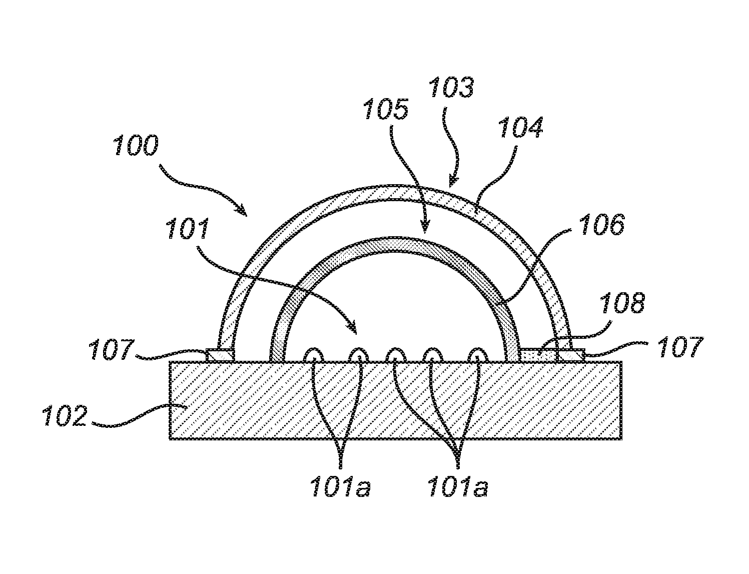
[0026]In FIG. 1 an embodiment of the light emitting arrangement 100 is shown in a cross-sectional view and seen from the side. The light emitting arrangement 100 comprises a sealing structure 103, which encloses a cavity 105, and which comprises a base part 102 and a light outlet member 104. Within the cavity, attached to the base part 102, is arranged a light source 101 comprising a plurality of LEDs 101a. The light outlet member 104 is attached to the base part 102 by means of a seal 107 arranged to seal the cavity 105. The arrangement 100 further comprises a remote wavelength converting member 106, which is attached to the base part 102 in the cavity 105 and arranged to receive light emitted by the LEDs. A getter 108 is arranged on the base part 102 within the cavity 105. The base part 102 further comprises or supports for instance electrical terminals and drive electronics, as understood by the person skilled in the art, although not explicitly shown.

[0027]The wavelength convert...


PUM


Abstract

The invention provides a light-emitting arrangement (100, 200, 300), comprising: a light source (101, 201, 301) adapted to emit light of a first wavelength; a wavelength converting member (106, 206, 306) comprising a wavelength converting material adapted to receive light of said first wavelength and to convert at least part of the received light to light of a second wavelength; a sealing structure (103) at least partially surrounding said wavelength converting member to form a sealed cavity (105, 205, 305) containing at least said wavelength converting member, said cavity containing a controlled atmosphere; and a getter material (108, 208, 308) arranged within said sealed cavity, wherein said getter material is adapted to operate in the presence of water and / or produces water as a reaction product. Such getter materials have high capacity for removal of oxygen from the atmosphere within the sealed cavity, such that a low oxygen concentration can be maintained within the cavity. Hence, the lifetime of the wavelength converting material may be prolonged.

Description

FIELD OF THE INVENTION[0001]The present invention related to light-emitting arrangements containing wavelength converting compounds which require a controlled atmosphere.BACKGROUND OF THE INVENTION[0002]Light-emitting diode (LED) based illumination devices are increasingly used for a wide variety of lighting applications. LEDs offer advantages over traditional light sources, such as incandescent and fluorescent lamps, including long lifetime, high lumen efficacy, low operating voltage and fast modulation of lumen output.[0003]Efficient high-power LEDs are often based on blue light emitting materials. To produce an LED based illumination device having a desired color (e.g., white) output, a suitable wavelength converting material, commonly known as a phosphor, may be used which converts part of the light emitted by the LED into light of longer wavelengths so as to produce a combination of light having desired spectral characteristics. The wavelength converting material may be applied...

Claims


Application Information

Patent Timeline
Patent Type & Authority Patents(United States)
IPC IPC(8): H05B33/04F21K99/00H01L51/52F21V31/00H05B33/14F21V31/03F21Y101/02
CPCH05B33/04F21K9/135F21K9/56H01L51/5259H05B33/14F21V31/00F21Y2101/02F21V31/03F21K9/232F21K9/64F21Y2115/10H10K50/846
Inventor HIKMET, RIFAT ATA MUSTAFACILLESSEN, JOHANNES FRANCISCUS MARIA
Owner SIGNIFY HLDG BV
Why Eureka
Try Eureka