
Method of and device for capturing 3D data of one or more airborne particles

a technology of airborne particles and 3d data, which is applied in the direction of instruments, vessel parts, vessel construction, etc., can solve the problems of limited to either point on a line, and achieve the effects of optimizing power output, reducing blade load, and optimizing power outpu

Inactive Publication Date: 2015-10-20
SIEMENS AG
View PDF17 Cites 2 Cited by
  • Summary
  • Abstract
  • Description
  • Claims
  • Application Information

AI Technical Summary

Benefits of technology

This patent describes a method and device for capturing 3D data of airborne particles, such as dust particles or water droplets, to determine wind field properties in order to optimize power output of a wind turbine. The device uses a plenoptic camera and known geometry and optical properties to determine the distance of a selected particle from the camera's plane of focus. This information can be used to adapt the pitch angle of the blades or reduce loads on the blades due to wind shear or wind gusts. The device also includes a tracer particles ejection mechanism to measure the aerodynamic properties of the rotor blades. The use of the device in a wind tunnel allows for the determination of the whole wind field with a single camera.

Problems solved by technology

LIDAR is most commonly used to capture wind speed and direction data, but it is limited to either points on a line or, with newer versions, a two-dimensional plane.

Method used


Image

  • Method of and device for capturing 3D data of one or more airborne particles
  • Method of and device for capturing 3D data of one or more airborne particles
  • Method of and device for capturing 3D data of one or more airborne particles

Examples


Embodiment Construction

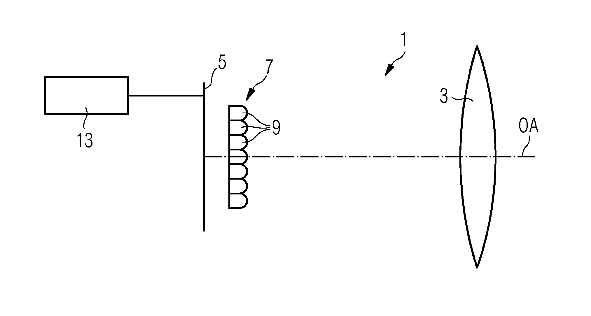
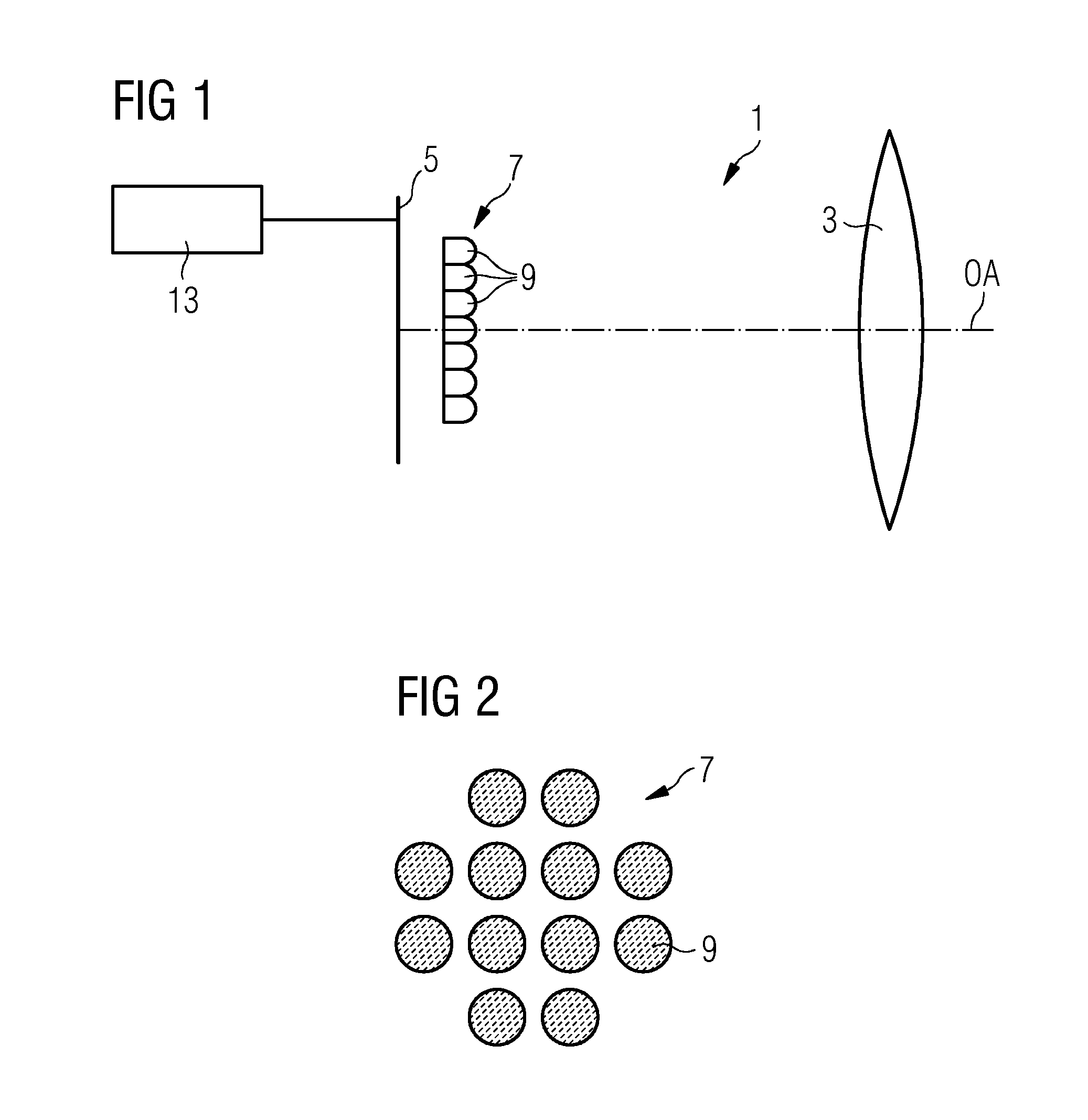
[0023]Prior to describing the method, the main optical components of a plenoptic camera will be described with respect to FIGS. 1 and 2.

[0024]FIG. 1 shows the arrangement of the main optical components of a plenoptic camera 1 in a section taken along the optical axis OA of the components. The plenoptic camera 1 comprises a main lens 3, an image sensor 5, which could be a CCD-sensor (CCD: charge coupled device) or a CMOS-sensor (CMOS: complementary metal oxide semiconductor), and a lenticular array 7, i.e. an array of microlenses 9, arranged in front of the image sensor 5. A view onto the lenticular array 7 in a direction along the optical axis OA is shown in FIG. 2.

[0025]One may think of each microlens 7 of the lenticular array as being a tiny camera that forms an image of the main lens aperture on the sensor 5. Since the mircolenses 9 of the lenticular array 7 are distributed in a plane perpendicular to the optical axis OA each tiny image formed by a microlens 9 represents a slight...


PUM


Abstract

Disclosed is a method of capturing 3D data of one or more airborne. At least one image of the one or more airborne particles is taken by a plenoptic camera of which the geometry and the optical properties of its optics are known, and the distance of a plane of focus with at least one selected particle of the one or more airborne particles from a defined reference location is determined by use of the captured image together with the known optical properties and the known geometry of the optics of the plenoptic camera.

Description

CROSS REFERENCE TO RELATED APPLICATIONS[0001]This application claims priority of European Patent Office application No. 11172225.2 EP filed Jun. 30, 2011. All of the applications are incorporated by reference herein in their entirety.FIELD OF INVENTION[0002]The present disclosure relates to a method of capturing 3D data of one or more airborne particles. In addition, the disclosure relates to a device for performing the method.BACKGROUND OF INVENTION[0003]Capturing large scale or small scale 3D wind data is, for example, of importance for validating aerodynamic properties of models in wind tunnels or other articles. In addition, 3D wind data may be used in control systems of wind turbines to optimize wind turbine efficiency or to take measures for counteracting expected loads.[0004]US 2006 / 0140764 A1 describes a wind turbine having a LIDAR (light detection and ranging) wind speed measurement apparatus for achieving wind control. LIDAR is most commonly used to capture wind speed and ...

Claims


Application Information

Patent Timeline
Patent Type & Authority Patents(United States)
IPC IPC(8): G01P5/26G01P5/00G01S5/16
CPCG01P5/26G01P5/001G01S5/16
Inventor SOERENSEN, EMIL HEDEVANG LOHSE
Owner SIEMENS AG
Learn More