Substances detection system and method

a detection system and substance technology, applied in the field of substances detection, can solve the problems of reducing affecting the detection efficiency of substances, so as to improve the detection efficiency, reduce the cost, and simplify the assembly

Active Publication Date: 2015-10-27
ANIKA STERILIS PTE LTD
View PDF33 Cites 3 Cited by
  • Summary
  • Abstract
  • Description
  • Claims
  • Application Information

AI Technical Summary

Benefits of technology

[0010]What is desired is a system and / or method having better performance, simpler assembly, reduced cost and / or greater reliability for field deployment, than the prior art. Also, the present invention will preferably provide sufficient selectivity and specificity for analyzing the complex chemical matrix that is normally encountered in sampling maritime containers, air cargo, luggage and the like.
[0012]The advantages of IMS detection, such as high sensitivity, good specificity, and fast detection rates can be more effectively utilized when the sample is preconditioned. A major difficulty with the use of IMS under field conditions is the heavily contaminated samples and complex chemical matrices often found in the field. These can cause detector overload and system contamination. Such conditions occur, for example, in forensic investigations following bombing incidents, and in the search of shipping containers for drugs and explosives. The problem arises within the ionization process where the background contaminants which are present in much greater abundance than the analytes of interest dominate the ionization process and preferentially take the available electrons or charge reservoir for ionization to the detriment of the analytes, such that limits of detection and selectivity are significantly degraded.
[0018]By pretreating the sample in the sample vaporization process, and separating it in a sample loop and in the GC column such that only analytes that are very close to those earmarked for detection are fed into the IMS, significant improvements in signal to noise ratio can result, and false alarm rates can be considerably reduced.
[0019]Chromatography is a very mature well established technique. The capillary columns contain liquid phases chemically bonded to the column walls. The passage of the vapour through the column is retarded to varying degrees depending upon carrier gas flow rates, column temperature and chemical properties of the compounds injected onto the column. Different chemicals will travel through the GC at different rates and emerge at different times. In the preferred form of the invention, the eluent portion of interest is taken to the detector, by time separation, while other fractions are allowed to bypass the detector (preferably IMS) as needed. This prevents unwelcome competition in the ionization process and / or overloading of the detector.
[0022]Simultaneously, potential analytes of interest are also delivered to a GC for conditioning and / or further separating (long cycle). Once separated, the potential analytes of interest are delivered to the IMS detector having been separated and cleaned more thoroughly than the short cycle potential substances of interest. Thus, if the short cycle identifies a substance of interest, that identification can either be confirmed as correct, or as a false alarm, by the long cycle. The long cycle result is more reliable because the long cycle provides a more thoroughly conditioned and separated sample to the detector.

Problems solved by technology

A major difficulty with the use of IMS under field conditions is the heavily contaminated samples and complex chemical matrices often found in the field.
These can cause detector overload and system contamination.
The problem arises within the ionization process where the background contaminants which are present in much greater abundance than the analytes of interest dominate the ionization process and preferentially take the available electrons or charge reservoir for ionization to the detriment of the analytes, such that limits of detection and selectivity are significantly degraded.

Method used


Image

  • Substances detection system and method
  • Substances detection system and method
  • Substances detection system and method

Examples


Embodiment Construction

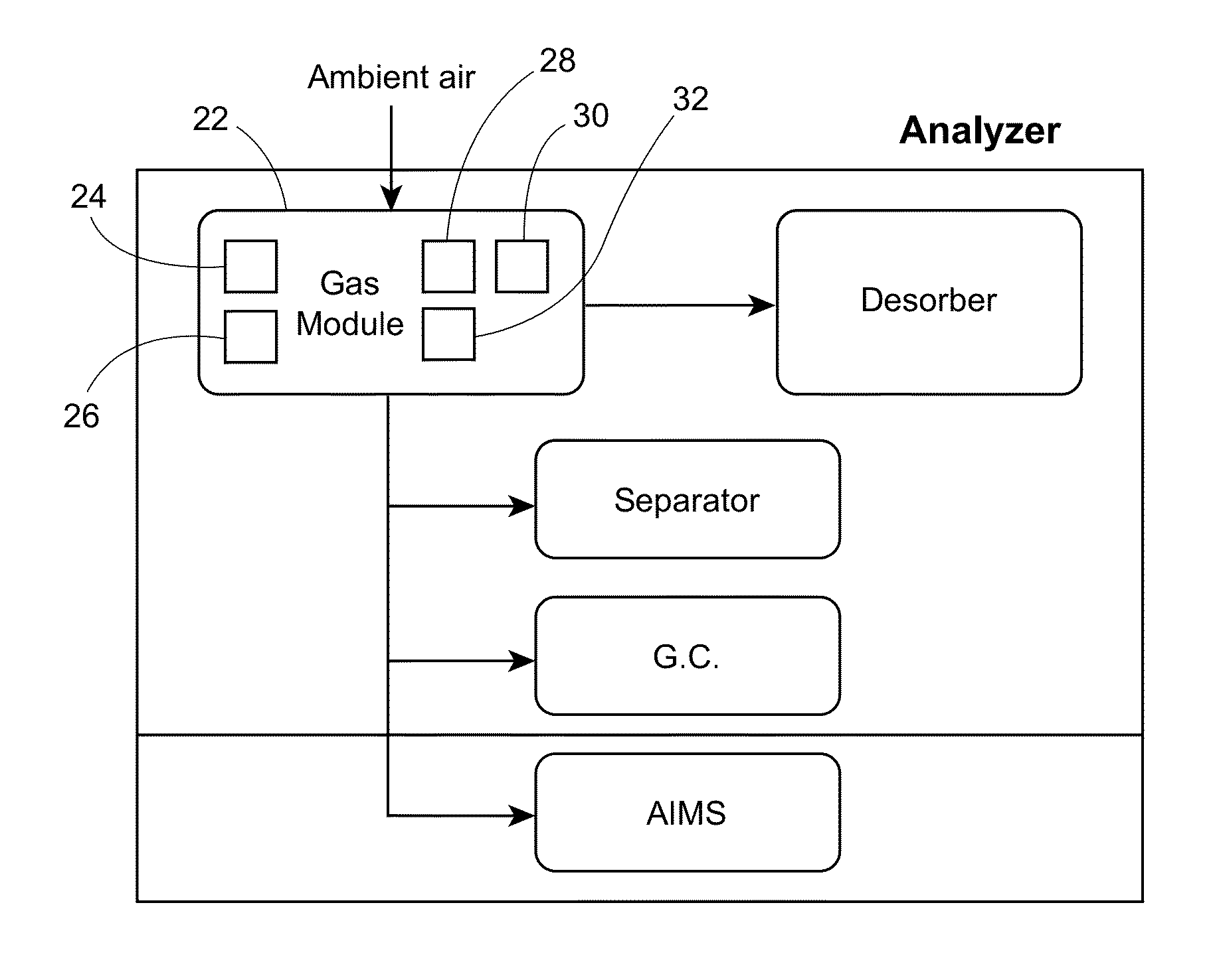
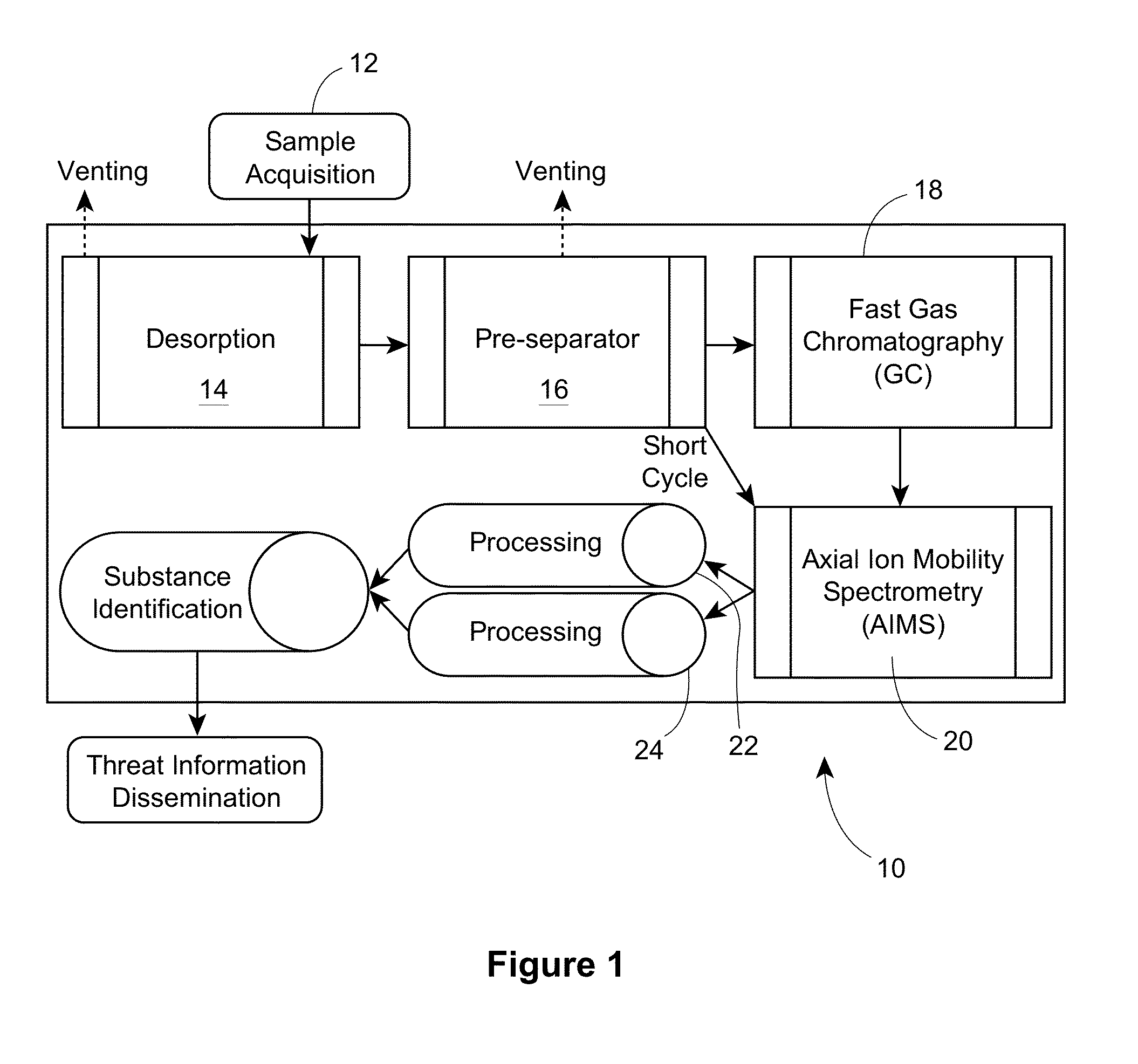
[0058]Referring now to FIG. 1, a schematic representation of the preferred analyser system 10, according to an aspect of the invention, is shown. The sample 12 is acquired through interfacing with desorber 14. Desorber 14 communicates with pre-separator 16, which communicates both with GC 18, and AIMS 20. Processing means 22 and 24 are in communication with AIMS 20, and the outputs of means 22, 24 are used to identify substances of interest, after which identification information is disseminated. In the preferred embodiment, a carrier gas (discussed below) carries the sample from the desorber 14, to the pre-separator 16, the GC 18 and the AIMS 20.

[0059]The sample may, for example, be positioned on a sample collection slide, card or filter disk sized and configured to interface with the desorber 14. Preferably, the desorber 14 includes means for ramping up temperature upon receipt of a sample to evaporate volatile compounds not of interest, thus cleaning the sample. These volatile co...


PUM

PropertyMeasurementUnit
boiling pointaaaaaaaaaa
ion mobility spectrometeraaaaaaaaaa
ion mobilityaaaaaaaaaa

Abstract

A system and methodology for the detection of threat substances is described. The detector system consists of a method to evaporate the sample into a primary separator and thermal release of trapped target materials into a secondary separator like conventional GC. The GC column is thermally ramped to elute all substances and the end of the column terminates into an atmospheric pressure chemical ionization source of an axial ion mobility spectrometer (AIMS). Both polarity ions are pulsed into a single construction separator tube at different timing. Their arrival time is detected on a collector plate, which allows registering their ion mobility spectra of both polarities for a single GC peak.

Description

CROSS REFERENCE TO RELATED APPLICATIONS[0001]This application is the national stage of International (PCT) Application No. PCT / CA2013 / 000412, filed Apr. 26, 2013, which claims the benefit of and priority to U.S. Provisional Patent Application Ser. No. 61 / 638,919, filed Apr. 26, 2012, the entire contents of each of which are herein incorporated by reference.FIELD OF THE INVENTION[0002]This invention relates to the field of substance detection (for example, explosives, narcotics, chemical warfare agents, environmental pollutants), which are typically but not necessarily threat substances.BACKGROUND OF THE INVENTION[0003]The increasing terrorist threat internationally has made it crucial to detect all kinds of explosives and other threat substances in order to provide security for important locations such as airports, border crossings, embassies, seaports, governmental buildings, power stations or transportation systems. A number of techniques for detecting threat substances are known,...

Claims


Application Information

Patent Timeline
Patent Type & Authority Patents(United States)
IPC IPC(8): B01D59/44H01J49/00H01J49/40G01N27/62H01J49/04
CPCG01N27/622H01J49/0409G01N33/22G01N1/2273G01N1/405G01N30/88G01N2001/022G01N30/7206
Inventor NACSON, SABATINOCRNATOVIC, ALEKSANDARWISEMAN, GEORGE
Owner ANIKA STERILIS PTE LTD
Why Eureka
Try Eureka