System and method for sensing intraocular pressure

a sensor and intraocular pressure technology, applied in the field of optical sensors, can solve the problems of reducing affecting the comprehensive understanding of the iop profile of individual patients, and requiring extreme care, so as to improve the sensitivity and strength of the readout signal, reduce the size of the sensor, and simplify the effect of sensor design

Active Publication Date: 2015-11-03
CALIFORNIA INST OF TECH +1
View PDF13 Cites 16 Cited by
  • Summary
  • Abstract
  • Description
  • Claims
  • Application Information

AI Technical Summary

Benefits of technology

[0012]In view of the foregoing, one aspect of the present invention provides the first engineered nanophotonics sensor for biological pressure sensing. Nanophotonic components reduce the size of the sensors, as well as improve the sensitivity and strength of the readout signals. Embodiments of the invention provide a highly miniaturized IOP monitoring system using a nanophotonics-based implantable IOP sensor with remote optical readout that can be adapted for both patient and research use. A handheld detector optically excites the pressure-sensitive nanophotonic structure of the IOP-sensing implant placed in the anterior chamber and detects the reflected light, whose optical signature changes as a function of IOP. Optical detection eliminates the need for large, complex inductive-coupling / capacitive-sensing (LC) structures and simplifies sensor design. The use of precisely engineered nanophotonic components improves the sensor's resolution and sensitivity, increases optical readout distance, and reduces its size by a factor of 10-30 over previously reported implants. Its small size and convenient optical readout allows more frequent and accurate self-tracking of IOP by patients in home settings. In addition, this technology can be adapted for use in monitoring large cohorts of animals to support glaucoma research and drug discovery.
[0013]Thus, according to embodiments of the present invention, automated and systematic monitoring of IOP profiles can be achieved. This leads to better definition of IOP fluctuations, that when combined with aggressive lowering of IOP, results in better clinical outcome. It allows physicians to improve patients' adherence to medication and detect suboptimal IOP control. It also provides more accurate IOP profiles for individually tailored pressure-lowering treatment, and improves understanding of the relationship between IOP and disease. With adaptation, it also allows convenient IOP monitoring in large groups of research animals to accelerated fundamental discovery and drug development.

Problems solved by technology

As glaucoma typically affects the elderly, the aging demographic trends indicate that this disease will continue to be an ever-increasing socioeconomic burden to society.
The inability of patients to easily monitor their own IOPs at different times of the day or during various daily activities hinders the comprehensive understanding of the IOP profile of individual patients and the possibility of custom-tailored IOP control.
However, achieving an acceptable level of accuracy and repeatability in animal IOP measurements requires anesthesia and extreme care.
Conducting such time-consuming measurements in large populations of animals is a major hurdle in glaucoma drug discovery.
However, both modalities have difficulties in providing reliable and repeatable readouts of actual IOP values inside the eye.
Since studies show that IOP varies widely throughout the day, quarterly measurements are poor representations of a patient's actual IOP profile.
Unfortunately, the operating principle of this device puts a limit on the miniaturization of the sensor.
Either the size of the sensor has to become large to achieve a longer transmission distance, or small devices lead to extremely short readout distances limit the practical use of the device.
For example, to read IOP at a 2 centimeter distance, the IOP sensor has to be at least around 3 millimeters in size, which is too large in terms of patient acceptance and interference with ocular function.
Unfortunately, IOP measurements in animals using tonometry require anesthesia and extreme care for repeatability.
Previously developed MEMS-based sensors are too large for use in rodent models, which make up more than 90% of the animal species used in glaucoma research.
For example, these implants may range in size from 1-3 mm and are difficult to use in rodents that have corneal diameters of about 3.5 mm.

Method used


Image

  • System and method for sensing intraocular pressure
  • System and method for sensing intraocular pressure
  • System and method for sensing intraocular pressure

Examples


Embodiment Construction

[0039]Systems and methods for sensing intraocular pressure (“IOP”) are described. In the following description, for purposes of explanation, numerous specific details are set forth in order to provide a thorough understanding of the exemplary embodiments. It is apparent to one skilled in the art, however, that the present invention can be practiced without these specific details or with an equivalent arrangement.

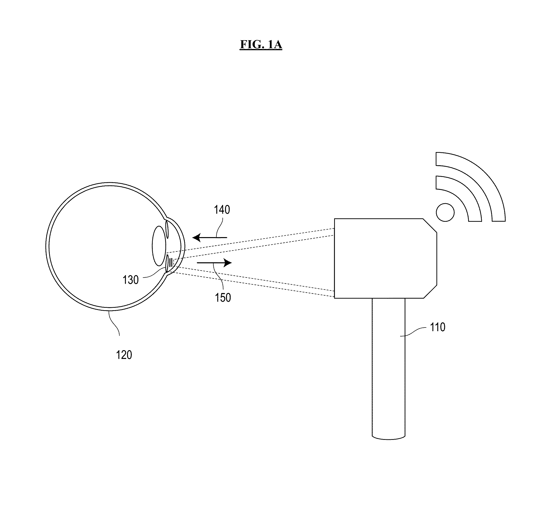
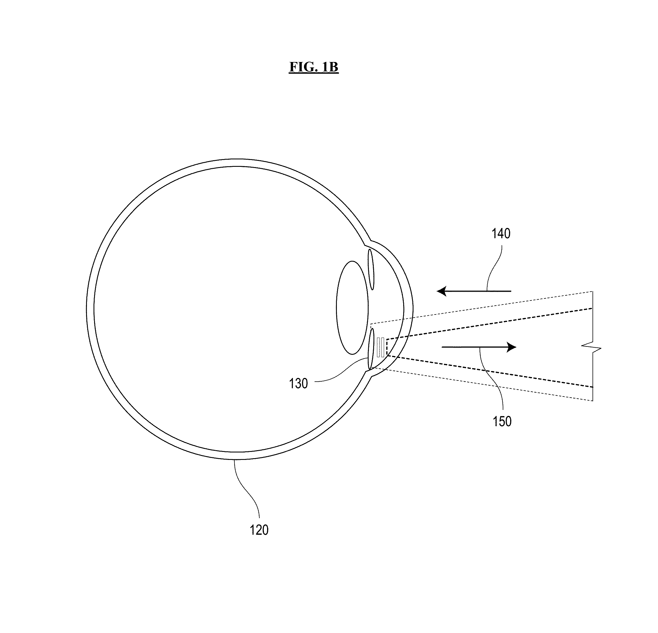
[0040]Referring now to the drawings, wherein like reference numerals designate identical or corresponding parts throughout the several views, FIGS. 1A and 1B are schematic diagrams of a system for sensing intraocular pressure in accordance with an embodiment of the invention. A battery-free IOP-sensing implant 130 with remote optical readout is inserted into the ocular anterior chamber of an eye 120, between the cornea and the iris. The sensor implant 130 is excited by an excitation beam 140 from an external light source built into a portable, handheld reader unit 110. The r...


PUM

PropertyMeasurementUnit
wavelengthaaaaaaaaaa
diameteraaaaaaaaaa

Abstract

Systems and methods of sensing intraocular pressure are described. An example miniaturized intraocular pressure (IOP) monitoring system is provided using a nanophotonics-based implantable IOP sensor with remote optical readout that can be adapted for both patient and research use. A handheld detector optically excites the pressure-sensitive nanophotonic structure of the IOP-sensing implant placed in the anterior chamber and detects the reflected light, whose optical signature changes as a function of IOP. Optical detection eliminates the need for large, complex LC structures and simplifies sensor design. The use of nanophotonic components improves the sensor's resolution and sensitivity, increases optical readout distance, and reduces its size by a factor of 10-30 over previous implants. Its small size and convenient optical readout allows frequent and accurate self-tracking of IOP by patients in home settings.

Description

BACKGROUND OF THE INVENTION[0001]1. Field of the Invention[0002]The present invention relates generally to optical sensors, and in particular, to a system and method for sensing intraocular pressure.[0003]2. Description of Related Art[0004]Glaucoma is a leading cause of blindness, affecting an estimated four million Americans and seventy million individuals globally. As glaucoma typically affects the elderly, the aging demographic trends indicate that this disease will continue to be an ever-increasing socioeconomic burden to society. Elevated intraocular pressure (“IOP”) is a major risk factor for glaucoma, and IOP monitoring is the single most important clinical management tool.[0005]Despite the pervasive use of IOP readings for disease monitoring and the clinically proven importance of the aggressive lowering of IOP, current clinical management is primarily based on only periodic snapshots of IOP in the doctor's office obtained every few months. The inability of patients to easil...

Claims


Application Information

Patent Timeline
Patent Type & Authority Patents(United States)
IPC IPC(8): A61B3/16G01L1/24G01L9/00B82Y5/00
CPCA61B3/16G01L1/247G01L9/0077B82Y5/00B82Y15/00
Inventor CHOO, HYUCKSRETAVAN, DAVIDKIM, MYUNG-KI
Owner CALIFORNIA INST OF TECH
Why Eureka
Try Eureka