Integrated sorbent injection and flue gas desulfurization system

a flue gas desulfurization and sorbent injection technology, which is applied in the direction of lighting and heating apparatus, emission prevention, separation processes, etc., can solve the problems of uncaptured energy that is leaving the boiler envelope (as heat in the flue gas) and reduce the boiler efficiency, so as to improve the boiler efficiency and plant heat rate, and ensure safe operation.

Active Publication Date: 2015-11-24
THE BABCOCK & WILCOX CO
View PDF9 Cites 6 Cited by
  • Summary
  • Abstract
  • Description
  • Claims
  • Application Information

AI Technical Summary

Benefits of technology

[0008]Disclosed herein are various methods and systems for reducing acid gas (e.g. SOx) emissions in a boiler flue gas stream with a pollution control system that uses a circulating dry scrubber (CDS) or a spray dryer absorber (SDA) for desulfurization by controlling SO3 concentration upstream of the air heater. Briefly, hydrated lime, i.e. a calcium hydroxide powder, is injected into the flue gas upstream of a heat recovery system component, for example between the boiler economizer and a regenerative air heater. This reduces the SO3 concentration and the acid dew point temperature (ADP) of the flue gas, permitting additional heat energy to be captured. Additionally, by reducing the ADP of the flue gas and lowering the temperature of the flue gas exiting the air heater, further improvements in boiler efficiency can be obtained.
[0013]In such a system, multiple ports are present for hydrated lime injection, allowing for a small fraction of the lime flow to be injected upstream of the air heater and the remainder to be added elsewhere within the desulfurization unit. The total flow of hydrated lime is no greater than that of a CDS-only installation (where hydrated lime is only injected in the circulating dry scrubber). Through application of this system, the same total flow of sorbent facilitates further advantages such as enhanced boiler efficiency (and thus plant efficiency and plant heat rate) while safely operating at a lower flue gas temperature.

Problems solved by technology

However, other combustion reactions with chemical components in the fuel result in undesirable byproducts.
By doing so, however, some of the energy that is leaving the boiler envelope (as heat in the flue gas) is not captured.
Unrecovered energy directly reduces the efficiency of the boiler, which has an unfavorable impact on the plant heat rate; the increased heat rate is equivalent to reduced plant efficiency.
Reduced boiler efficiency also degrades the plant heat rate by requiring additional fan power to handle increased air and gas flows, as well as additional power in fuel and ash handling systems.

Method used


Image

  • Integrated sorbent injection and flue gas desulfurization system
  • Integrated sorbent injection and flue gas desulfurization system
  • Integrated sorbent injection and flue gas desulfurization system

Examples


example 1

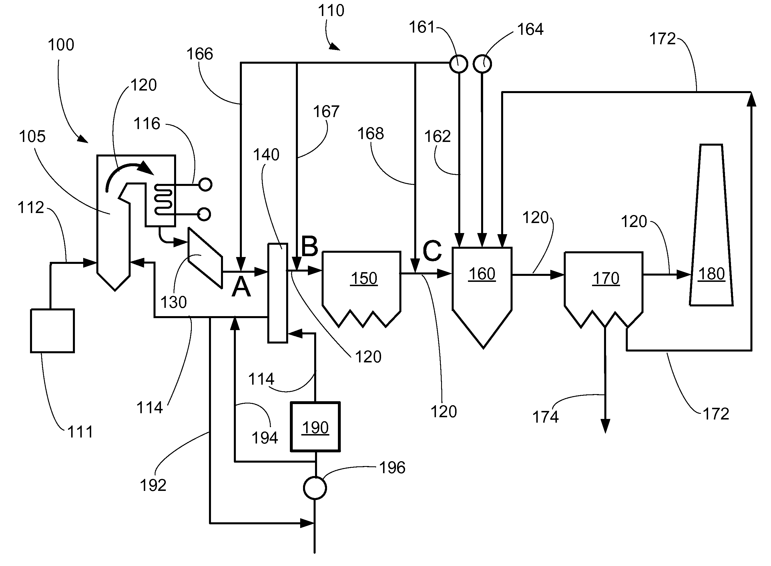
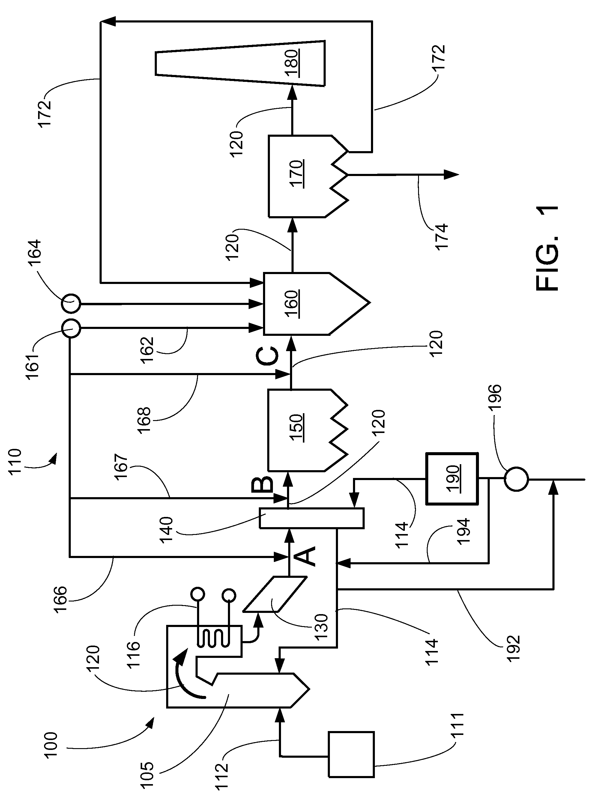
[0063]In a proposed application involving medium sulfur coal, the expected acid dew point temperature (ADP) based on uncontrolled SO3 formation was calculated to be 289° F. leaving the air heater. Application of dry sorbent injection (DSI) upstream of the air heater lowered the expected ADP to 256° F. The difference between these temperatures (33° F.) represents energy that could be safely recovered with typical heat transfer equipment and no additional corrosion risk. To realize this benefit by transferring additional heat, the boiler's economizer and air heater surfaces can be increased. The boiler efficiency gain associated with this method was approximately 0.8%. Resulting auxiliary power consumption improved as well, and total sorbent consumption was reduced by the same 0.8% (since 0.8% less flue gas and associated emissions were produced). CO2 emissions were likewise reduced by 0.8% because less fuel is combusted. Because of the improved boiler efficiency realized in the integ...

example 2

[0065]As illustrated in FIG. 5, applying dry sorbent upstream of the air heater permits the safe operating flue gas exit temperature (at the hot flow pass outlet) to be reduced to 240° F. If CDS is chosen for desulfurization, the integrated system could be designed for 250° F., thus achieving 30° F. reduction from the case when dry sorbent is not applied upstream (280° F.). If SDA is chosen for desulfurization, a temperature of 270° F. can be designed for. Again, total sorbent consumption is no greater than the initial “uncontrolled” scenario; in fact, sorbent consumption is reduced since less fuel is combusted and less SO3 is generated in the boiler.

example 3

[0066]In this example illustrated in FIG. 6, the safe operating air heater exit gas temperature for the flue gas can be reduced from 320° F. to 280° F. Both CDS and SDA can operate effectively at 280° F., so the integrated system permits this 40° F. reduction in flue gas temperature. Again, the total sorbent consumption has been reduced as described above. The overall emissions coming from the boiler decrease due to reduced fuel flow (better plant efficiency).


PUM

PropertyMeasurementUnit
temperatureaaaaaaaaaa

Abstract

An integrated sorbent injection, heat recovery, and flue gas desulfurization system is disclosed. A dry sorbent is injected into the flue gas upstream of the air heater. This reduces the acid dew point temperature, permitting additional heat energy to be captured when the flue gas passes through the air heater. The flue gas then passes through a desulfurization unit and through a baghouse, where solids are captured. The capture of additional heat energy permits the overall boiler efficiency to be increased while safely operating at a lower flue gas temperature. The integrated system consumes no greater quantity of sorbent than conventional methods but provides the benefit of improved plant heat rate.

Description

CROSS-REFERENCE TO RELATED APPLICATION[0001]This application claims priority to U.S. Provisional Application Ser. No. 61 / 904,939, filed Nov. 15, 2013 entitled “Integrated Sorbent Injection and Flue Gas Desulfurization System”. U.S. Provisional Application Ser. No. 61 / 904,939, filed Nov. 15, 2013 entitled “Integrated Sorbent Injection and Flue Gas Desulfurization System” is incorporated by reference herein in its entirety.BACKGROUND[0002]The present disclosure relates to a flue gas desulfurization (FGD) system which is used to remove particulates, gases, and other contaminants from flue gas produced during combustion of medium- to high-sulfur fuels. In particular, sulfur dioxide (SO2), sulfur trioxide (SO3), HCl, and other acid gases can be captured; the acid dew point temperature of the flue gas can be reduced, and associated equipment corrosion can be lessened. Sorbents are used more effectively in the present system. This, among other things, increases boiler efficiency, enhances ...

Claims


Application Information

Patent Timeline
Patent Type & Authority Patents(United States)
IPC IPC(8): B01D53/50B01D53/83B01D53/81B01D53/86
CPCB01D53/508B01D53/8631B01D2251/404B01D53/505B01D53/869B01D2251/602B01D2251/604B01D2251/606B01D2257/2045B01D2258/0283F23J15/003F23J15/006F23J2215/20F23J2217/101F23J2217/102F23J2219/10F23J2219/60
Inventor WARREN, ERIC MGAYHEART, JEB WSILVA, ANTHONY A
Owner THE BABCOCK & WILCOX CO
Why Eureka
Try Eureka