Method and apparatus for forming structures of polymer nanobeads

a technology of nanobeads and printing structures, applied in photomechanical equipment, instruments, optical elements, etc., can solve the problems of large overhead costs, high cost of lithographic techniques, and often observed non-uniform polymer patterns, and achieve the effect of removing the surface roughness of printed polymer

Active Publication Date: 2015-11-24
MASSACHUSETTS INST OF TECH
View PDF24 Cites 0 Cited by
  • Summary
  • Abstract
  • Description
  • Claims
  • Application Information

AI Technical Summary

Benefits of technology

[0012]In another embodiment, the disclosure relates to identifying the polymer's thermoplastic properties to substantially eliminate the surface roughness of printed polymer. In accordance with the embodiment, inkjet printing method is used to deposit printed polymer on a substrate. The substrate having printed polymer thereon is exposed to one or more solvents for a duration of time necessary to subject the print surface of the polymer to render a smooth and substantially flat surface.

Problems solved by technology

MEMS typically require specialized processes and packaging for each product and cannot recover the large overhead costs without being significantly more expensive.
However, lithographic techniques are expensive and time-consuming.
Non-uniform polymer patterns are often observed as a result of inkjet printing.
The non-uniform patterns have been attributed to the complicated ink wetting and drying process on ink-impermeable substrate surface.
The conventional approaches have failed to produce a substantially flat printed PMMA surface suitable for high-tech applications.
The PMMA layer produced with conventional method also lacks the desired optical properties.

Method used


Image

  • Method and apparatus for forming structures of polymer nanobeads
  • Method and apparatus for forming structures of polymer nanobeads
  • Method and apparatus for forming structures of polymer nanobeads

Examples


experiment 1

[0056

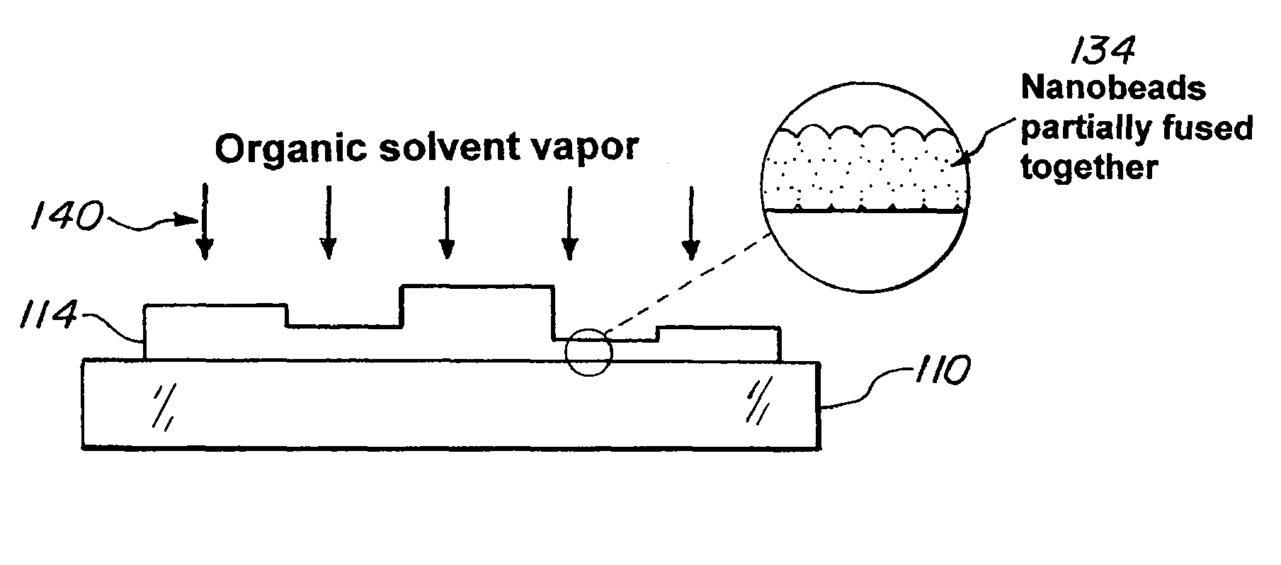
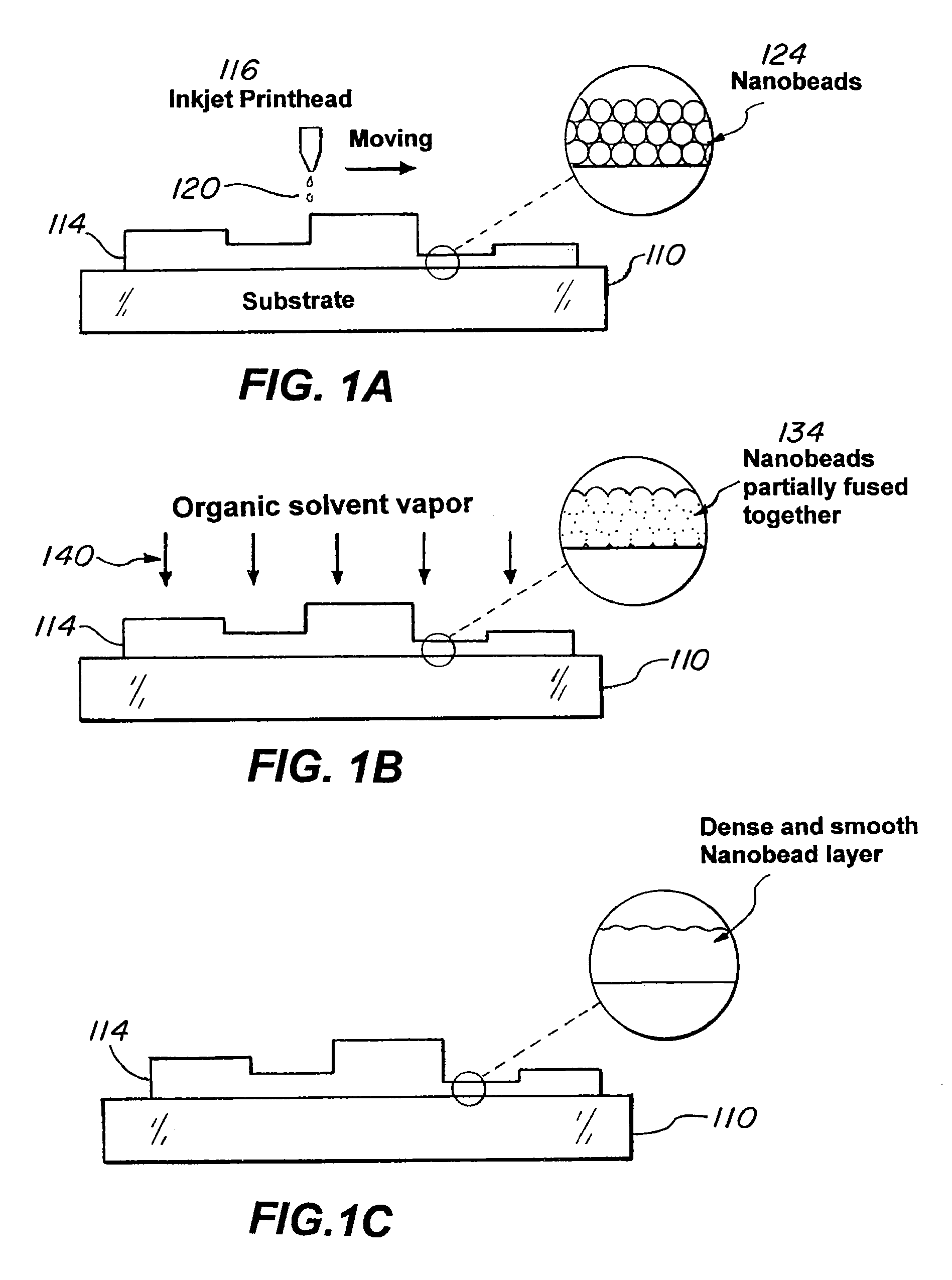
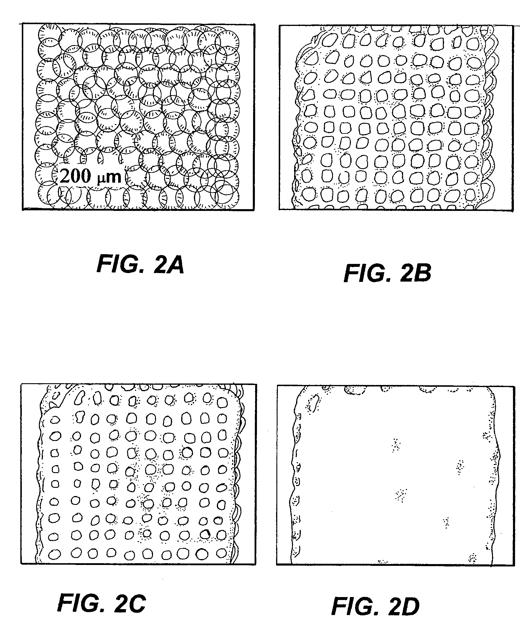
[0057]An experiment was devised to study the effectiveness of using inkjet printing method together with solvent vapor post-treatment to form smooth PMMA features. Namely, a smooth PMMA spacer and structure layers for MEMS surface micromachining application were devised by inkjet printing aqueous PMMA nanosphere suspensions and solvent annealing nanobead structures in Acetone.

[0058]The starting ink comprised of PMMA nanobead-water binary mixture and was prepared by stirring PMMA nanobeads (surface pretreated with surfactant to increase stability of the mixture) in de-ionized water for 2 hours. The final mixture was filtered through a 5 um polytetrafluoroethylene (PTFE) filter. Microscopic slides were used as substrate. Before use, the glass substrates were degreased by ultrasonification in 2% Micro-90 solution, de-ionized water and boiling isopropanol each for 5 minutes and then dried with nitrogen gas. Ink containing different PMMA loading concentrations were printed onto clea...

experiment 2

[0063

[0064]A MEMS structure was devised with the structural and sacrificial materials separately optimized. The two structures were combined together to complete the surface micromachining process. In theory, the process can consist of three stages: depositing and processing of the sacrificial material, depositing and processing of the structural material, and removal of the sacrificial material. In practice, however, the process is more complicated because of the difficulty with confining the amount of ink needed to obtain 1 μm thick structural film. The large volume would overcome the ink's surface tension and subsequently spill out to the surrounding area, resulting in a thinner and poorer defined film. To counteract this, external mechanisms are needed to keep the silver ink confined during the drying and densification steps.

[0065]In an embodiment of the disclosure, silver ink is confined by depositing secondary PMMA features. These secondary features act as barriers or dams ess...


PUM

PropertyMeasurementUnit
diameteraaaaaaaaaa
melting pointaaaaaaaaaa

Abstract

The disclosure relates to providing printed structures of polymer that have substantially flat printed surfaces. In one embodiment, the disclosure relates to a post-printing treatment apparatus for receiving a substrate supporting a polymer printing thereon. The polymer can be PMMA or other suitable polymer. In a related embodiment, the polymer defines a thermoplastic polymer having a glass transition temperature. The apparatus can comprise of a chamber, and input manifold, an exhaust manifold, a solvent reservoir and a gas reservoir. The solvent reservoir provides one or more solvent systems adapted to chemically bind, and potentially react, with the polymer. The gas reservoir provides one or more gases for drying the substrate and printed polymer after the solvent treatment step. In one application, a substrate having printed surface thereon is placed in the chamber and exposed to the solvent system for sufficient period of time to provide substantially flat print surfaces.

Description

[0001]This invention was made with government support. Accordingly, the government has certain rights in this invention.BACKGROUND[0002]1. Field of the Invention[0003]The disclosure relates to printing structures made of polymer nanobeads. More specifically, the disclosure relates to a method and apparatus for providing printed structures of polymer nanobeads that have substantially flat printed surfaces and provide improved optical properties.[0004]2. Description of Related Art[0005]Microelectromechanical systems (MEMS) fabrication falls into two categories: bulk and surface micromachining. The former consists of removing significant portions of the underlying substrate to define the desired features, while the latter consists of addition and subsequent removal of materials on top of the base substrate. Both categories rely on semiconductor industry manufacturing methods, especially lithography, a technique which relies on mask layers to selectively protect the covered portions whi...

Claims


Application Information

Patent Timeline
Patent Type & Authority Patents(United States)
IPC IPC(8): G02B6/138B05D3/10B05D3/04G03F7/16G02B6/12
CPCG02B6/138B05D3/04B05D3/0453B05D3/107G02B2006/12071G03F7/168
Inventor BULOVIC, VLADIMIRCHAPARALA, MURALICHEN, JIANGLONGLAM, ERIC WING-JINGLEBLANC, VALERIESCHMIDT, MARTIN A.
Owner MASSACHUSETTS INST OF TECH
Why Eureka
Try Eureka